


8
104193
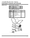
PORTABLE FORCED AIR HEATER
115,000 Btu/Hr H.S.I. Series
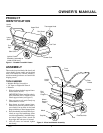
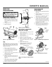
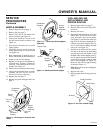
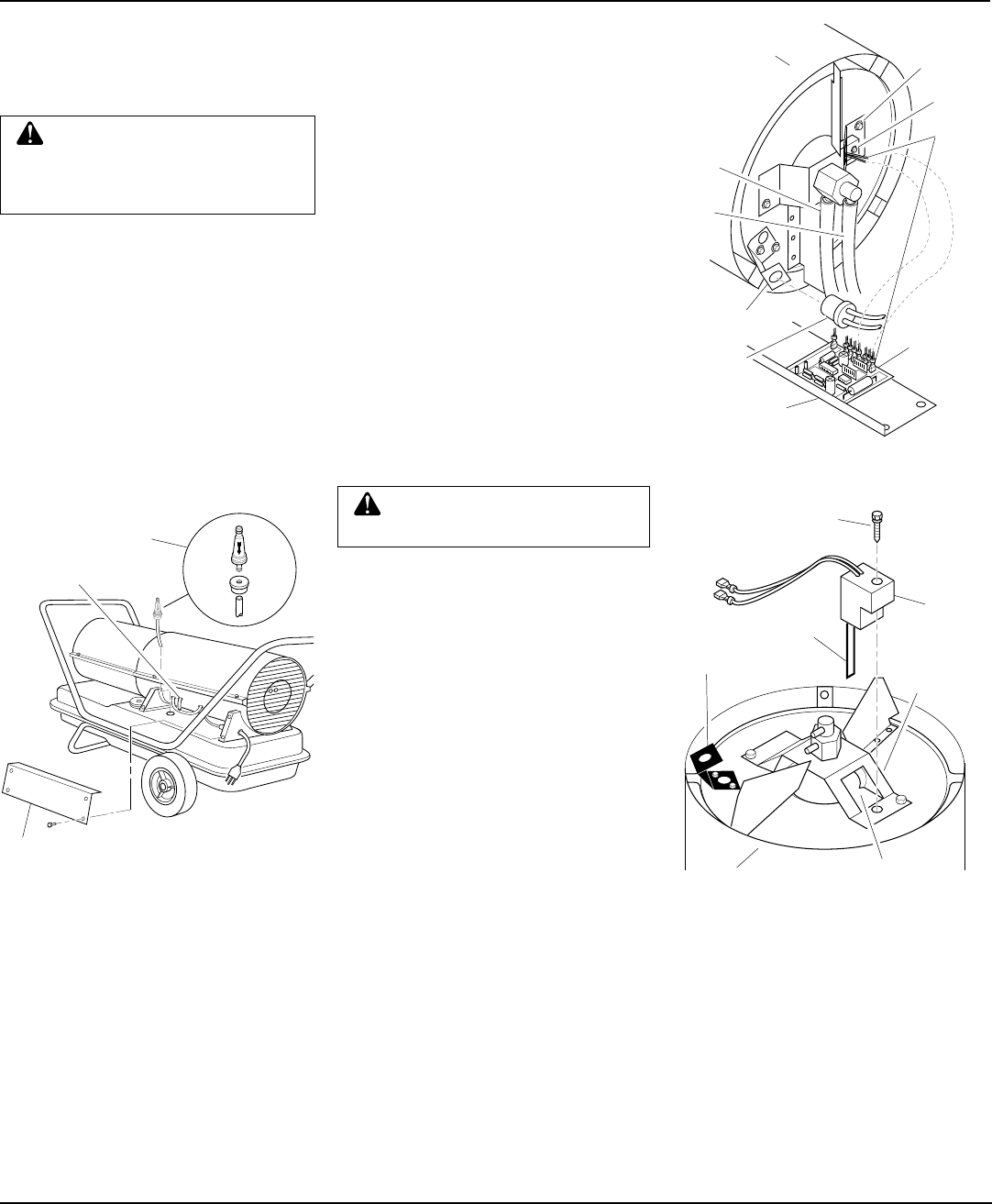
Figure 9 - Fuel Filter Removal
SERVICE
PROCEDURES
Continued
FUEL FILTER
1. Remove side cover screws using 5/16"
nut-driver.
2. Remove side cover.
3. Pull upper fuel line off fuel filter neck.
4. Carefully pry bushing, fuel filter, and
lower fuel line out of fuel tank.
5. Wash fuel filter with clean fuel and re-
place in tank.
6. Attach upper fuel line to fuel filter neck.
7. Replace side cover.
Side Cover
Fuel Filter, Bushing,
and Lower Fuel Line
Upper Fuel Line
WARNING: Never service
heater while it is plugged in, oper-
ating, or hot. Severe burns and
electrical shock can occur.
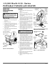
IGNITOR
1. Remove upper shell and fan guard (see
page 7).
2. Remove fan (see page 7).
3. Remove 4 side cover screws with a
5/16" nut driver. Remove side cover
(see Figure 9).
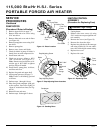
4. Disconnect ignitor wires (yellow) from
ignition control assembly (see Figure
10). Pull the ignitor wires up through
the hole in the lower shell.
5. Disconnect fuel line hose and air line
hose. Remove photocell from photocell
bracket (see Figure 10).
6. Remove combustion chamber. Stand
combustion chamber on end with nozzle
adapter bracket on top (see Figure 11).
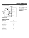
7. Remove ignitor screw with a 1/4" nut
driver. Carefully remove ignitor from
nozzle adapter bracket.
8. Carefully remove replacement ignitor
from styrofoam packing.
9. Carefully guide ignitor into opening in
nozzle adapter bracket. Do not strike
ignitor element. Attach ignitor to nozzle
adapter bracket with screw using a
1/4" nut driver (see Figure 11). Torque
8 to 15 in. lbs. Do not over torque.
10. Replace combustion chamber.
11. Route the ignitor wires back down through
the hole in the lower shell. Connect wires
to the ignition control assembly.
12. Replace side cover (see Figure 9).
13. Connect fuel line hose and air line hose
to nozzle assembly. See Fuel and Air
Line Replacement and Proper Routing,
page 9.
14. Replace photocell in photocell bracket.
15. Replace fan (see page 7).
16. Replace fan guard and upper shell (see
page 7).
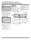
Combustion
Chamber
Photocell
Bracket
Photocell
Assembly
Air
Line
Hose
Fuel
Line
Hose
Photocell
Bracket
Ignitor
Wires
Nozzle
Adapter
Bracket
Ignition
Control
Assembly
Side Cover
Figure 10 - Disconnecting Ignitor Wires
from Ignition Control Assembly
Ignitor
Ignitor Screw/Washer
Assembly
Nozzle
Adapter
Bracket
Nozzle Adapter
Bracket Opening
Ignitor
Element
CAUTION: Do not bend or strike
ignitor element. Handle with care.
Combustion
Chamber
Figure 11 - Ignitor Replacement
Ignitor