


10
104193
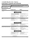
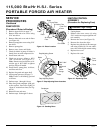
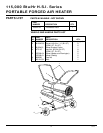
PORTABLE FORCED AIR HEATER
115,000 Btu/Hr H.S.I. Series
SERVICE
PROCEDURES
Continued
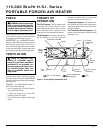
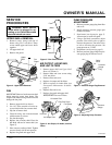
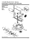
Sandpaper
.003"/.004"
Gap
Measured
With
Feeler
Gauge
Blade
Rotor
Gap Adjusting Screw
Gap Adjusting Screw
Insert
Rotor
Air Output
Filter
Blade
Pump Plate
Air Intake Filter
Filter End
Cover
Fan Guard
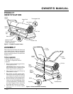
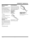
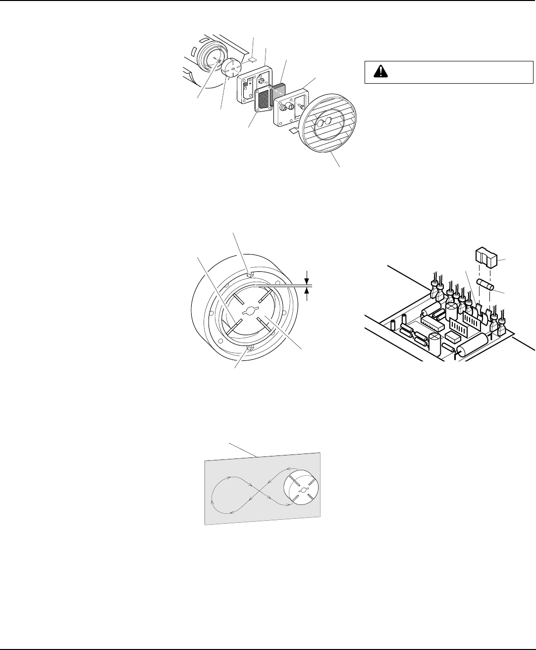
Figure 16 - Rotor Location
Figure 17 - Gap Adjusting Screw Locations
Figure 18 - Sanding Rotor
PUMP ROTOR
(Procedure if Rotor is Binding)
1. Remove upper shell (see page 7).
2. Remove filter end cover screws using
5/16" nut-driver.
3. Remove filter end cover and air filters
(see Figure 16).
4. Remove pump plate screws using 5/16"
nut-driver.
5. Remove pump plate.
6. Remove rotor, insert, and blades.
7. Check for debris in pump. If debris is
found, blow out with compressed air.
8. Install insert and rotor.
9. Check gap on rotor. Adjust to .003"/
.004" if needed (see Figure 17).
Note:
Rotate rotor one full turn to in-
sure the gap is .003"/.004" at tightest
position. Adjust if needed.
10. Install blades, pump plate, air filters,
and filter end cover.
11. Replace fan guard and upper shell.
12. Adjust pump pressure (see page 7).
Note:
If rotor is still binding, proceed
as follows.
13. Perform steps 1 through 6 above.
14. Place fine grade sandpaper (600 grit)
on flat surface. Sand rotor lightly in
“figure 8” motion four times (see Fig-
ure 18).
15. Reinstall insert and rotor.
16. Perform steps 10 through 12 above.
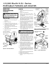
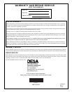
IGNITION CONTROL
ASSEMBLY
(Procedure for Replacing Fuse)
WARNING: High Voltage
1. Unplug heater.
2. Remove side cover screws (4) using
5/16" nut-driver to expose ignition con-
trol assembly.
3. Remove fuse cover (see Figure 19).
4. Remove fuse from fuse clips.
5. Replace fuse with fuse of the same type
and rating (GMA-10). Do not substi-
tute a fuse with a higher current rating.
6. Replace fuse cover.
7. Replace side cover.
Figure 19 - Replacing Fuse
Fuse
Cover
Fuse
Clips
Fuse