


6
7
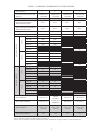
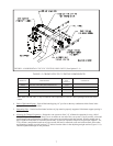
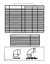
TABLE 1.5: CROWN CPVC/PVC VENTING COMPONENTS
CROWN PN DESCRIPTION
USED ON
VENT
OPTION #
COMMENTS
230595 CPVC/PVC VENT KIT, BWC070/090/120/151 1,2,5,6
230596 CPVC/PVC VENT KIT, BWC150 3,7
230597 CPVC/PVC VENT KIT, BWC225 4,8
230873 PVC CONCENTRIC TERMINAL 2,6 Use with BWC070/090/120/151 Only
Note: BWC070/090/120/151 may be ordered with components in 230595 vent kit packaged inside the boiler
carton.
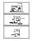
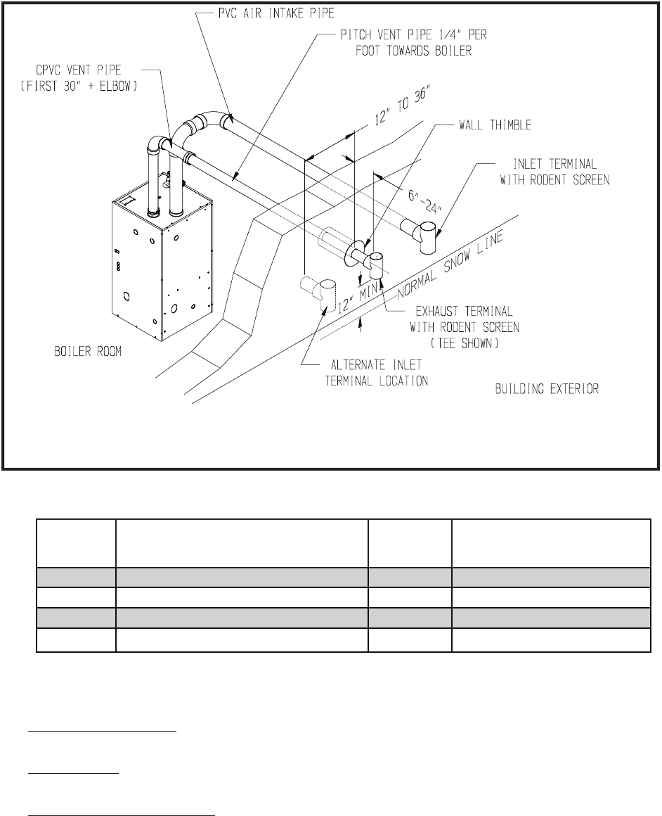
FIGURE 1.4: HORIZONTAL CPVC/PVC VENTING, BWC150/225 (Vent Option #3, 4)
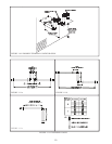
Pitch of Horizontal Piping4. - Pitch all horizontal piping 1/4” per foot so that any condensate which forms in the
piping will run towards the boiler.
Supporting Pipe5. - Vertical and horizontal sections of pipe must be properly supported. Maximum support spacing is
four feet.
Allowing for Thermal Expansion6. - Design the vent system to allow 3/8” of thermal expansion for every 10ft of
CPVC/PVC pipe. The boiler will always act as an anchor to one end of the vent system. If at all possible, select and
install hangers and wall thimbles so that the vent system can expand towards the terminal. When a straight run of
pipe exceeds 20ft and must be restrained at both ends, an offset or expansion loop must be provided (Figures 1.11a,
1.11b). When a straight horizontal run of pipe exceeds 20ft and is restrained at one end with an elbow at the other,
avoid putting a hanger or guide less than “Y” inches from the elbow in the adjoining straight section (Figure 1.11c).
Thermal expansion ttings are not permitted.