


2
3
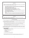
WARNING
Failure to vent this boiler in accordance with these instructions could cause ue gas to enter the building
resulting in severe property damage, personal injury, or death:
Use of the BWC boiler with CPVC/PVC venting requires a special vent kit available from Crown •
Boiler Company. Do not attempt to vent the boiler using either CPVC/PVC without the use of the
appropriate vent kit called for in this manual.
Do not apply thermal insulation to vent pipe or ttings.•
Do not interchange vent systems or materials unless otherwise specied.•
Do not obtain combustion air from within the building. •
Do not install a barometric damper, vent damper, or drafthood on this boiler.•
Unless otherwise noted, the• use of CPVC is required where the vent pipe passes through enclosed
spaces and through wall penetrations.
Do not use cellular core PVC (ASTM F891).•
Pitch the vent piping as called for in these instructions to prevent condensate from pooling in the •
venting.
Starting at the boiler, the rst 30” of straight pipe, and the rst 90 degree elbow, in the vent system •
must be CPVC. PVC may only be used in the vent system downstream of this CPVC piping.
A. Vent System Design
There are several different ways to vent BWC series boilers. This installation supplement covers installation of
those vent systems that employ CPVC and PVC plastic pipe. Refer to the BWC installation manual when installing a
vent system using stainless steel or concentric PPs venting.
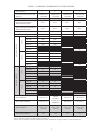
When CPVC/PVC pipe is used, there are two basic ways to vent a BWC boiler, each having several variations:
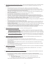
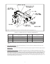
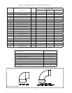
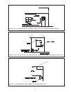
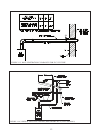
• Horizontal (“Side Wall”) Twin Pipe Venting (Table 1.1) - Vent system exits the building through an outside
wall. Combustion air and ue gas are routed between the boiler and the terminal using separate pipes.
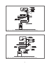
• Vertical Twin Pipe Venting (Table 1.12) - Vent system exits the building through a roof. Combustion air and
ue gas are routed between the boiler and the terminal using separate pipes.
All of these systems are considered “direct vent” because in all of them air for combustion is drawn directly from
the outdoors into the boiler. A description of all of these venting options are shown in Tables 1.1 and 1.12. One of
the vent option columns in Tables 1.1 or 1.12 must match the planned vent and air intake system exactly. In addition,
observe the following guidelines:
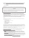
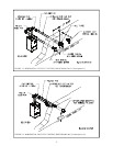
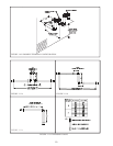
CPVC/PVC Adaptor Kits1. - The use of CPVC/PVC venting on BWC boilers requires the use of a special kit. Each
kit consists of the following principle components:
Adaptor/s for the Vent and Intake Connections•
30” Section of Straight CPVC Pipe•
CPVC Elbow•
(2) PVC Termination Tees•
(2) Rodent Screens•
(1 ea.) Can PVC/CPVC Primer and Cement•
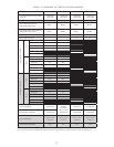
Part Numbers for each kit are shown in Table 1.5
NOTE: Models BWC070, 090, 120 and 151 may be ordered from the factory with the above components
packaged in the boiler. When this is done the vent adaptor may be shipped installed on the boiler.
CAUTION
Moisture and ice may form on the surfaces around the vent termination. To prevent deterioration,
surfaces should be in good repair (sealed, painted, etc.).