


16
17
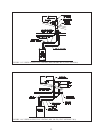
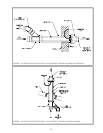
Assemble the vent system, starting at the boiler: 2.
The CPVC elbow and the 30” straight section of CPVC provided with the kit must be used before a.
transitioning to PVC. If necessary, the 30” straight section of CPVC may be cut at any location and the
CPVC elbow inserted between the two resulting segments.
When cutting CPVC or PVC pipe, use a miter saw or a saw designed to cut PVC pipe. Use a miter box or b.
other method to cut pipe squarely. De-burr both the inside and outside of the cut end.
Dry t all vent components before assembly. c.
Lubricate the gasket in the vent adaptor with water. Insert the rst straight section of CPVC into the vent d.
adaptor and tighten the hose clamp.
Clean all CPVC and PVC components with the appropriate primer before cementing. Cement the vent e.
system together, starting at the boiler and following the instructions provided on the cans of cement
and primer. Use the cement provided with the kit to assemble all CPVC components and to make all
connections between CPVC and PVC components. If additional cement/primer is needed, use cement/
primer that are designed for use with the plastics being joined (CPVC and/or PVC).
Depending on the layout of the vent system, the rst piece of PVC vent will be connected to either the f.
CPVC elbow or the end of a section of CPVC pipe. In the latter case, use a PVC coupling to connect the
rst piece of PVC to the last section of CPVC.
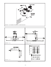
Assemble the rest of the vent system, being sure to pitch horizontal sections back towards the boiler 1/4”/ft. g.
Support the vent at intervals not exceeding 4ft.
Maintain the clearances from the vent pipe outlined in Part A of this manual. If exiting the exterior wall h.
using PVC pipe, use half of an appropriately sized wall thimble (or a sheet metal plate) on the exterior of
the building, to provide a weather tight seal while maintaining the proper clearance in the wall penetration.
Seal the joint between the pipe and the wall plate using RTV applied on the exterior side of the wall. This
sealant must not restrain the expansion of the vent pipe.
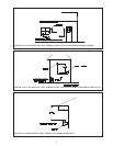
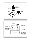
Installation of Air intake System3. - Start assembly of the air intake system at the boiler. Assembly of the air intake
system is done in the same manner as the vent system except as follows:
The rst piece of air intake pipe on the BWC150 and BWC 225 is installed over the intake adaptor installed a.
in Step (1i). This piece of pipe is secured to the adaptor using at least one sheet metal screw (drill a
clearance hole in the PVC intake pipe). Seal the joint between the intake pipe and the adaptor with RTV.
All intake piping may be PVC.b.
There is a 0” minimum clearance between the air intake piping and all types of construction.c.
To the extent possible, pitch horizontal air intake piping towards the outside . d.
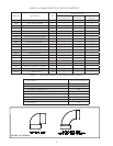
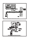
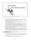
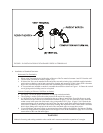
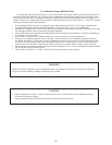
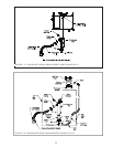
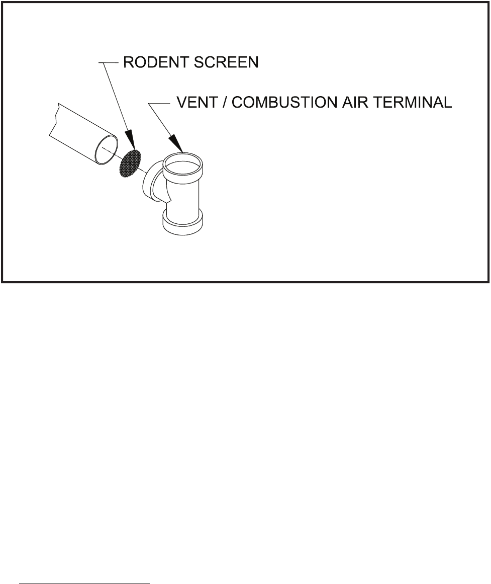
FIGURE 1.19: INSTALLATION OF STANDARD HORIZONTAL TERMINALS