


4
5
Approved vent components and materials - The adaptor kits listed in Table 1.5 are required to connect the venting 2.
to the boiler. Starting at the boiler, the rst 30 inches of the vent system, and the rst elbow, must be CPVC. In
addition, use only pipe that meets the following standards:
CPVC - ASTM F441•
PVC - ASTM D2665•
The primer and cement used must be designed for use with the venting materials being joined (PVC, CPVC or
CPVC to PVC).
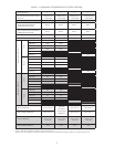
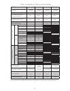
Maximum Vent and Air Intake Lengths3. - The maximum length of the vent air intake piping depends upon the
vent option selected and the boiler size. See Table 1.1 or 1.12 for the maximum vent lengths. In horizontal
vent systems, the lengths shown in Table 1.1 are in addition to the rst 90 elbow. For vertical vent systems, the
maximum vertical vent lengths shown in Table 1.12 are in addition to two 90 elbows. If more elbows are desired, the
maximum allowable vent length must be reduced by the amount shown in Table 1.7 for each additional elbow used.
Termination ttings are never counted.
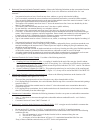
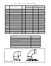
The elbows supplied in the CPVC/PVC vent kit are “standard radius” elbows. It is recommeded that all eld
supplied elbows must be “1/4 Bend” (Sanitary 90 El) or “Long Sweep 1/4 Bend” type elbows (Figure 1.8). In this
manual “sanitary” and “long sweep” elbows are treated as having the same equivalent length.
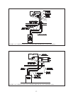
Example:
A 3” twin pipe horizontal CPVC/PVC vent system is planned for a horizontally vented BWC120 which has the
following components in the vent system:
1 ft CPVC Straight Pipe•
90 CPVC Elbow (Supplied in Crown vent kit)•
1-1/2 ft CPVC Straight Pipe•
Coupling•
10 ft PVC Straight Pipe•
90 PVC Elbow (Sanitary Elbow Design)•
15 ft PVC Straight Pipe•
PVC Tee Terminal•
The Vent Option #1 column in Table 1.1 describes a horizontal direct vent system using 3” CPVC and PVC pipe.
Fromthiscolumn,weseethataBWC120mayhaveaventlengthofupto100ft.TherstCPVC90degreeelbowis
not considered. From Table 1.7, we see that the equivalent length of the 90 PVC elbow is 4ft and that the equivalent
length of the coupling is 0ft. The total equivalent length of the planned venting system is therefore:
1ft(StraightCPVC)+0ft(rstCPVC90Elbow)+1.5ft(StraightCPVC)+0ft(Coupling)+10ft
(Straight PVC) +
4ft (PVC 90 Elbow) + 15ft
(Straight PVC)
+ 0ft (Tee Terminal) =
31.5ft.
Since Table 1.1 shows a maximum allowable vent length of 100ft, the planned vent system length is acceptable.
Minimum Vent and Air Intake Lengths 4. - Observe the minimum vent lengths shown in Table 1.1.
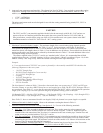
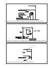
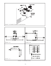
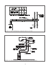
Permitted Terminals for Horizontal Venting (Vent Option #1-3)5. - Use one of the following terminals:
PVC Teesa. - PVC Tees are used for both the inlet and vent. They are the same size as the connected vent
or intake system and are installed with the run vertical as shown in Figures 1.2 and 1.4. Rodent screens are
installed in the side connection of the Tee where it is connected to the vent or intake pipe. Terminal Tees and
rodent screens are provided with the CPVC/PVC vent kit.
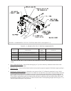
PVC Tees on Snorkelsb. - If desired, the PVC Tees terminations may be installed on snorkels as shown in Figure
1.10. When this is done, all exterior piping except for the termination Tees themselves must be counted when
calculating the equivalent length. The maximum vertical run of the snorkel is 5ft. Observe all restrictions on the
location of the Tee terminal described in Paragraph 6.
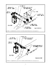
Crown Concentric Terminc. al (PN 230873 ) - This optional terminal may be used in place of the Tees on the
BWC070, 090, 120, and 151 (Figure 1.3). It may not be used on the BWC150 or 225.
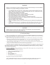
CAUTION
The CPVC and PVC vent materials supplied with this boiler do not comply with B149.1.S1-07 and are not
approved for use in Canadian jurisdictions that require that vent systems be listed to ULC S636-2008. In
these jurisdictions, vent this boiler using one of the AL29-4c stainless steel vent systems shown in the BWC
installation manual or a listed ULC S636 Class II - 90°C venting system.