


14
15
B. Assembly of CPVC/PVC Vent Systems
WARNING
Failure to follow the instructions could result in ue gas leakage into the combustion air or indoor air, resulting in
unsafe or unreliable operation.
All CPVC vent components (supplied with the boiler) must be used for near boiler vent piping before •
transitioning to Schedule 40 PVC (ASTM 2665) components for the remainder of the system.
The use of cellular core PVC (ASTM F891) is prohibited.•
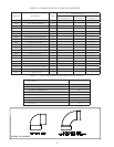
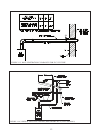
The use of CPVC is required where venting passes through chase ways and through walls with clearances less •
than shown in Figure 1.13.
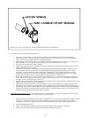
Never leave the boiler in operation without the silicone gas sample cap in place• (Figure 1.17, 1.18)
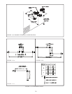
Install the vent adaptor and intake adaptor on the boiler. 1.
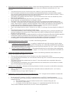
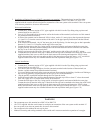
BWC070, 090, 120, 151 - If the CPVC/PVC vent/intake adaptor is not factory installed, install the vent/intake
adaptor as shown in Figure 1.17.
If the boiler has been supplied with a different vent adaptor, remove the six #10 sheet metal screws which a.
attach it to the boiler. Remove the old adaptor from the boiler (this may be easier if a twisting motion is
applied to the collar while removing it).
Attach the self adhesive gasket supplied with the stainless steel vent/intake adaptor to the bottom of the b.
adaptor.
Lubricate the brown gasket in the female end of the plastic vent stub (inside the boiler) with a few drops of c.
water.
Push the vent/intake adaptor onto the boiler with a slight twisting motion. Make sure that this vent adaptor d.
is inserted at least 1” into the boiler stub.
Secure the collar ange to the top of the boiler with the (6) #10 x 1/2” sheet metal screws supplied with the e.
vent kit or those removed in Step (a).
Verify that the silicone gas sample cap is in place (Figure 1.17).f.
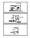
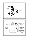
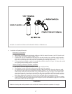
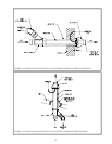
BWC150, 225 - Install the vent and air inlet adaptors as shown in Figure 1.18.
Remove the hose clamp shipped on the BWC150 or 225 vent collar.a.
Bend the three hose clamp tabs on this collar outward slightly.b.
Clean the exterior of the male end of the CPVC adaptor with an alcohol pad.c.
Apply a ¼” wide bead of high temperature silicone approximately ½ inch from the male end of the adaptor. d.
Also apply a ¼” bead of silicone along the rst 2 ½” of the longitudinal weld.
Insert the male end of the adaptor into the boiler vent collar until it bottoms out.e.
Apply an additional bead of silicone over the outside of the joint and smooth out.f.
Replace and tighten the clamp on the vent collar.g.
Verify that the silicone gas sample cap is in place (Figure 1.18).h.
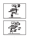
Attach the 1/2” ID Clear tubing provided to the condensate drain connection (Upper 1/2” tube) as shown in i.
Figure 1.18. Secure with one of the hose clamps provided.
Route the tubing down the right side panel and into the 1-3/8” knockout located in the lower portion of this j.
panel. Be sure to remove all burrs from the knockout to prevent the hose from being punctured.
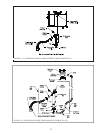
Remove the plug and black gasket ring from the bottom of the condensate trap located under the boiler k.
(Figure 1.24)
Replace the original gray trap plug with the white tapped plug. Screw the 90 degree hose barb provided into l.
this white plug (Figure 1.24).
Attach the other end of the 1/2” ID tubing to the 90 degree hose barb and secure with the remaining hose m.
clamp (Figure 1.24).
Slip the air inlet adaptor into the intake collar on the top of the boiler as shown in Figure 1.18. Secure with n.
at least one #10 sheet metal screw.