


6
7
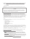
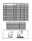
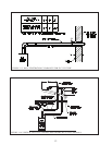
Horizontal Vent and Air Intake Terminal Location6. - Observe the following limitations on the vent terminal location
(also see Figure 1.9). When locating a concentric terminal, observe the limitations outlined below for “vent
terminals”.
Vent terminal must be at least 1 foot from any door, window, or gravity inlet into the building.•
For Tee terminals, maintain the correct clearance and orientation between the vent and air intake terminal. •
The vent and air intake terminals must be at the same height and their center lines must be between 12 and 36
inches apart. Both terminals must be located on the same wall.
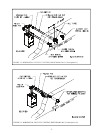
The bottom of all terminals must be at least 12” above the normal snow line. In no case should they be less •
than 12” above grade level.
The bottom of the vent terminal must be at least 7 feet above a public walkway. •
Do not install the vent terminal directly over windows or doors.•
The bottom of the vent terminal must be at least 3 feet above any forced air inlet located within 10 feet.•
USA Only: A clearance of at least 4 feet horizontally must be maintained between the vent terminal and gas •
meters, electric meters, regulators, and relief equipment. Do not install vent terminal over this equipment. In
Canada, refer to B149.1 Installation Code for clearance to meters, regulators and relief equipment.
Do not locate the vent terminal under decks or similar structures.•
Top of vent terminal must be at least 5 feet below eves, softs, or overhangs. Maximum depth of overhang is 3 •
ft.
Vent terminal must be at least 6 feet from an inside corner.•
Under certain conditions, water in the ue gas may condense, and possibly freeze, on objects around the vent •
terminal including on the structure itself. If these objects are subject to damage by ue gas condensate, they
should be moved or protected.
If possible, install the vent and air intake terminals on a wall away from the prevailing wind. Reliable operation •
of this boiler cannot be guaranteed if these terminals are subjected to winds in excess of 40 mph.
Air intake terminal must not terminate in areas that might contain combustion air contaminates, such as near •
swimming pools. See the installation manual for more information on possible contaminates.
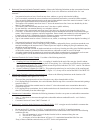
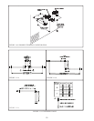
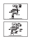
Permitted Terminals for Vertical Venting7. - Use either of the following terminals:
Coupling On Vent, 180 Bend On Inleta. - A coupling is installed in the end of the vent pipe. Install a rodent
screen between this coupling and the last piece of vent piping. Use a 180 bend or two 90 elbows to make the
inlet termination (Figures 1.14, 1.16). Rodent screens are provided with the CPVC/PVC vent kit. The elbow/s
and coupling must be procured locally.
Crown Concentric Terminal (PN b. 230873) - This optional terminal may be used in place of the coupling and
180 bend on the BWC070, 090, 120, and 151 (Figure 1.15). It may not be used on the BWC150 or BWC225.
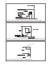
Vertical Vent Terminal Locations (Vent Options 5,6)8. - Observe the following limitations on the location of all
vertical vent terminals (see Figures 1.14 - 1.16):
The top of the vent pipe must be at least 2 feet above any object located within 10 feet.•
For Coupling/Elbow terminations, the vertical distance between top of the vent and air inlet terminal openings •
must be at least 12”.
The bottom of the air inlet terminal must be at least 12” above the normal snow accumulation that can be •
expected on the roof.
For Coupling/Elbow terminations, the air intake terminal must be located on the roof and must be no further •
than 24” horizontally from the exhaust pipe.
Clearances to Combustibles9. - Maintain the following clearances from the vent system to combustible construction:
Vent - 1” (also observe clearances through both combustible and non-combustible walls - see 10 below)•
Air Intake - 0”•
Concentric Portion of • Crown 230873 Terminal - 0”
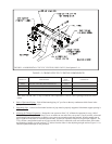
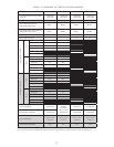
Running PVC Vent Pipe Inside Enclosures and Through Walls10. - PVC vent pipe must be installed in a manner that
permits adequate air circulation around the outside of the pipe:
Do not enclose PVC venting - Use CPVC in enclosed spaces, even if PVC is installed upstream. •
PVC venting may not be used to penetrate combustible or non-combustible walls unless all of the following •
conditions are met:
The wall pentration is at least 66 inches from the boiler as measured along the vent.a.
The wall is 12” thick or lessb.
An airspace of at least that shown in Figure 1.13 is maintained around the OD of the vent.c.
If any of these conditions cannot be met, use CPVC for the wall pentetration.