


48
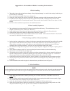
A. Before Installing
1) Thoroughly inspect the cast iron heat exchanger for any shipping damage, i.e. cracks in the castings, broken lugs or
punctures due to mishandling.
2) Do not use the heat exchanger if there is any damage to it.
3) Inspect the joints between the sections for openings. Reseal any openings with high temperature silicone sealant..
4) Keep the base in the shipping carton until it is time to perform the assembly. This keeps foreign material from
contaminating the burners or creating other hazards. Do not use the base assembly if there are any signs of visible
damage.
5) Review all of the installation requirements in this installation manual.
B. Base Assembly Preparation
1) The combination base-burner-manifold is shipped assembled from the factory. (The combination gas valve is
shipped assembled and can be found in the "Base Box".)
2) Smear a thin layer of silicone in several places across the top of the base to adhere the fiber gasket strip.
3) Install the fiber gasket strip, which was shipped in the "Base Box" (Figure A1).
4) Place the base assembly in the location where the boiler is to be installed. Refer to Section III and IV in the installa-
tion manual for additional information on placement.
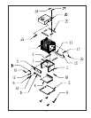
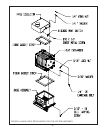
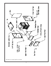
C. Heat Exchanger and Flue Collector Installation
1) Position the heat exchanger above the base with the return connection located toward the front of the boiler and the
lugs, located on each end of the boiler, centered over the studs, which are on each end of the base (Figure A1).
Lower the heat exchanger over the studs, taking care not to disturb the studs which may push out if the heat
exchanger comes in contact with them. Also, take care not to disturb the ceramic fiber gasket.
2) Once the heat exchanger has been placed on the base, inspect the gasket for proper seal. Repair or replace gasket if
necessary.
3) Secure the heat exchanger with 5/16" lock nuts with nylon inserts and washers from the hardware bag.
4) Loosen nuts on tie rods until they are finger tight.
5) Fiber gasket strips are used to seal the flue collector to the heat exchanger (this is the same material used between
the heat exchanger and base). Install this gasketing on the top of the heat exchanger (Figure A1). A few dabs of
silicone may be used to keep this gasketing from shifting when the flue collector is installed.
6) Install the flue collector as shown in Figure A1. Secure with the 1/4-20 carriage bolt, nuts, and washers provided.
7) Carefully inspect the joint between the flue collector and the heat exchanger to verify that the gasket is properly
positioned.
8) Install the blocked vent switch using the #8 sheet metal screw provided as shown in Figure A1.
Appendix A: Knockdown Boiler Assembly Instructions
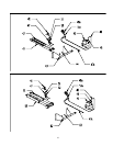
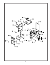
D. Jacket Installation
1) Attach the diverter Panel to the vestibule panel using two #10 sheet metal screws. Install these screws in the
outside holes.
2) Slip this diverter/vestibule panel assembly behind the draft diverter opening in the draft diverter assembly (Figure
A2). Attach to the diverter assembly using #10 sheet metal screws.
3) Attach the right side panel to the base and vestibule panel using four #10 sheet metal screws.
4) Orient the rear jacket panel so that the two notches are up. Slip the rear panel under the flange on the rear of the
side panel installed in the previous step and secure with three #10 sheet metal screws.
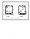
NOTE
Before installing the jacket, make sure to plug any tappings which are not going to be used. Also make sure that no tappings
are plugged which will be needed. See Figure A3 of this appendix, as well as Parts XIII and IX of the installation manual.
47