


35
XIII Troubleshooting
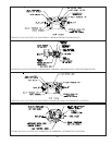
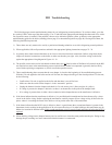
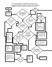
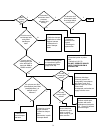
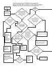
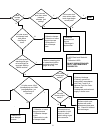
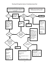
The following pages contain troubleshooting charts for use in diagnosing control problems. To use these charts, go to the
box marked “Start” at the top of the chart on page 35 or 37 and follow the appropriate path though the chart until a box with a
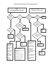
list of possible causes is reached. If the problem is known to be within the ignition system, go directly to the appropriate
troubleshooting guide for the boiler (standing pilot on page 39 or intermittent ignition on page 40). In using these charts, the
following should be kept in mind:
1) These charts are only meant to be used by a professional heating technician as an aid in diagnosing control problems.
2) Where applicable, follow all precautions outlined in the appropriate lighting instructions on pages 25 - 28.
3) In general, these charts assume that there are no loose or miswired electrical connections. Before using these charts,
inspect all electrical connections on the boiler to make sure that they are tight. Also, check the wiring on the boiler
against the appropriate wiring diagram in Figures 16 - 19.
4) The possible causes at the end of each branch in these charts are not listed in order of likelihood. All controls on the BSI
are tested at least once in the manufacturing process and a defective control or component is generally the least likely
cause. Before replacing a component, try to rule out all other possible causes.
5) These troubleshooting charts assume that the vent damper is closed at the beginning of the troubleshooting process.
With the 120 volts applied to the boiler and no call for heat, the damper should go to the closed position. If it does not,
do the following:
• Confirm that 120 volts is applied to the boiler and that there is no call for heat.
• Make sure that the switch on the damper is in the “automatic” position.
• Unplug the harness from the damper and check for 24 volts across pin #1 (blue) and pin #4 (yellow).
• If voltage is present, the damper is defective or there is an obstruction in the path of the damper blade.
• If no voltage is present, there is either a loose connection in the damper harness or the transformer is defective.
6) If the charts indicate that the transformer is defective, it is possible that this transformer has been destroyed by a short
circuit in the boiler wiring. Before replacing the transformer, carefully inspect all low voltage wiring on the boiler for
places where it is touching the frame of the boiler or wiring on the other side of the transformer.
7) If the charts indicate that the R8225 relay is defective, there is a good chance that a second transformer is present in the
thermostat circuit, resulting in the application of 48 volts across the relay coil. In older buildings, this transformer may be
hidden in a location far from the boiler. If this second transformer exists, it must be found and removed before the R8225 is
replaced.
8) When checking voltage across damper harness pins, be careful not to insert the meter probes into the pins. Doing so may
damage the pin, resulting in a loose connection when the harness is reconnected.
34