


10
9
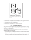
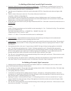
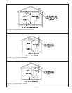
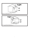
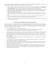
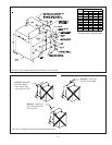
14) Vent damper installation is mandatory on all sizes from the BSI069 to BSI276. The BSI310 through BSI379 may be ordered
with or without vent damper. If supplied, install vent damper (see Figure 9) as follows:
a) Open vent damper carton and remove installation instructions. Read the instructions thoroughly before proceeding.
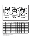
Verify that vent damper is same size as draft diverter outlet. See Figure 1. Unpack vent damper carefully. Do not force
closed damper blade. Forcing vent damper closed may result in damaged gear train and void warranty.
b) Vent damper is factory shipped having approximately ¾” diameter hole in the vent damper blade, which must be left
open for boilers equipped with standing pilot, and should be plugged on boilers with an intermittent pilot system,
using the plug supplied with the damper.
Mount the vent damper on the flue collar without modification to either and secure with sheet metal screws. Make
sure screws do not interfere with damper blade operation. Vent damper blade position indicator must be visible to
users.
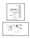
c) The damper wire harness is shipped wired into the boiler junction box. Plug the loose end of this harness into the
damper and secure the flexible conduit to the damper using a connector nut provided.
d) Install vent connector pipe and vent fittings from vent damper outlet to chimney or gas vent. Secure with sheet metal
screws and support as required.
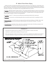
Removing an Existing Boiler from a Common Chimney
In some cases, when an existing boiler is removed from a common chimney, the common venting system may be too large for
the remaining appliances. At the time of removal of an existing boiler the following steps shall be followed with each appliance
remaining connected to the common venting system placed in operation, while the other appliances remaining connected to
the common venting system are not in operation.
a) Seal any unused opening in the common venting system.
b) Visually inspect the venting system for proper size and horizontal pitch and determine there is no blockage or
restriction, leakage, corrosion and other deficiencies which could cause an unsafe condition.
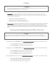
c) Insofar as practical, close all building doors and windows and all doors between the space in which all the appliances
remaining connected to the common venting system are located and other spaces of the building. Turn on clothes
dryers and any appliance not connected to the common venting system. Turn on any exhaust fans, such as range
hoods and bathroom exhausts, so they will operate at maximum speed. Do not operate a summer exhaust fan. Close
fireplace dampers.
d) Place in operation the appliance being inspected. Follow the lighting instructions. Adjust thermostat so the appliance
will operate continuously.
e) Test for spillage at the draft hood relief opening after five (5) minutes of main burner operation. Use the flame of a
match or candle, or smoke from a cigarette, cigar, or pipe.
f) After it has been determined that each appliance remaining connected to the common venting system properly vents
when tested as outlined above, return doors, windows, exhaust fans, fireplace dampers and any other gas-burning
appliances to their previous condition of use.
g) Any improper operation of the common venting system should be corrected so the installation conforms with the
National Fuel Gas Code, ANSI Z223.1. When resizing any portion of the common venting system, the common
venting system should be resized to approach the minimum size as determined using the appropriate tables in the
National Fuel Gas Code, ANSI Z223.1.