


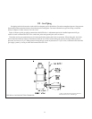
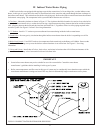


20
BSI Control System – Sequence of Operation
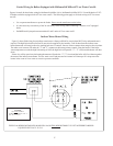
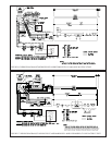
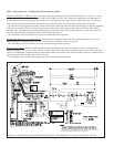
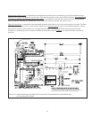
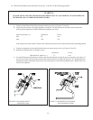
(Refer to Figures 16 through 19 for ladder and connection diagrams)
Sequence of Operation, Standing Pilot
1) When the boiler is energized, 24 volts is immediately applied to terminals “1” (blue) and “4” (yellow) on the vent
damper. Assuming that there is no call for heat, and that the damper switch is in the “automatic” position, the damper will
close. On boilers equipped with Hydrolevel CG400A probe type low water cut-offs, voltage is also always applied to
terminals “1” (blue) and “2” (yellow) on the low water cut-off to power the water level sensing circuit. On boilers equipped
with #67 float type low water cut-offs, power is always applied to terminal “2” on the #67 LWCO.
2) Assuming that water is above the cut-off level, power will appear at terminal “3” on the CG400 LWCO or terminal “1” on the
#67 LWCO.
3) Assuming that steam pressure is below the pressure limit setting, power will appear on one side of relay contact 1R1
(Gray lead). Relay 1R is the R8225 mounted under the junction box.
4) A call for heat from the thermostat energizes relay coil 1R causing contacts 1R1 to make. Current then flows through
contacts 1R1 to pin terminal “2” (orange) at the vent damper and the damper opens.
5) Once the vent damper is fully open, an end switch inside the damper will make, energizing pin “3” (red) at the damper.
6) Current passes from terminal “3” on the vent damper though the flame rollout and blocked vent (“spill”) switches.
Under normal conditions, both of these switches are made and voltage will therefore immediately appear across the combi-
nation gas control (“gas valve”) terminals “TH” and “TR”.
7) When the boiler is first placed into operation, the pilot must be lit. The pilot heats a thermocouple which generates a small
amount of electricity sufficient to hold open the safety shut-off valve in the combination gas control.
The circuit connecting
the thermocouple and the safety shut-off valve is self contained and completely independent of all other wiring on the boiler.
This safety shut-off valve is upstream of the 24 volt valves in the gas control which open in response to a call for heat. If the
pilot is not lit, the safety shut-off valve will remain closed and gas will not reach the 24 volt valves.
8) Assuming that the pilot is established and proven by the thermocouple, the application of 24 volts across the combina-
tion gas valve terminals energizes the redundant 24 volt solenoid valves in the combination gas control, resulting in gas
flow through the control and burner operation.
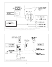
Sequence of Operation, Intermittent Ignition
1) When the boiler is energized, 24 volts is immediately applied to terminals “1” (blue) and “4” (yellow) on the vent
damper. Assuming that there is no call for heat, and that the damper switch is in the “automatic” position, the damper will
close. On boilers equipped with Hydrolevel CG400A probe type low water cut-offs, voltage is also always applied to
terminals “1” (blue) and “2” (yellow) on the low water cut-off to power the water level sensing circuit. On boilers equipped
with #67 float type low water cut-offs, power is always applied to terminal “2” on the #67 LWCO.
2) Assuming that water is above the cut-off level, power will appear at terminal “3” on the CG400 LWCO or terminal “1” on the
#67 LWCO.
3) Assuming that steam pressure is below the pressure limit setting, power will appear on one side of relay contact 1R1
(Gray lead). Relay 1R is the R8225 mounted under the junction box.
4) A call for heat from the thermostat energizes relay coil 1R causing contacts 1R1 to make. Current then flows through
contacts 1R1 to pin terminal “2” (orange) at the vent damper and the damper opens.
5) Once the vent damper is fully open, an end switch inside the damper will make, energizing pin “3” (red) at the damper.
6) Current passes from terminal “3” on the vent damper though the flame rollout and blocked vent (“spill”) switches.
Under normal conditions, both of these switches are made and voltage will therefore immediately appear across terminals
“24V” and “24V (GND)” on the ignition module.
7) Upon application of voltage across the “24V” and “24V (GND)” terminals, the ignition module will start an ignition spark
at the pilot and apply 24 volts across the pilot valve (terminals “PV” and “MV/PV”).
8) Once the pilot is established, the pilot flame will act as a diode, converting the AC current at the electrode to a half
wave DC current at the pilot’s ground strap. This DC current flows through the boiler to the “GND (BURNER)” connection
on the ignition module. For the ignition module to recognize that a pilot flame is present, the DC current flowing into this
terminal must be in excess of approximately 1.0 uA.
9) Once the ignition module detects the presence of a pilot flame, voltage is applied across the main valve (terminals “MV”
and “MV/PV”), opening the valve and establishing main flame.
10) The way in which the ignition module handles failure to establish pilot or the loss of an already established pilot
depends upon the exact ignition module supplied with the boiler. For more information on module operation, consult the
ignition module instructions supplied with the boiler or the local Crown representative.
19