


Crestron Commercial Lighting Design Guide GreenLight Options–CAEN Enclosures
Doc. 4775A 44
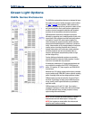
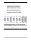
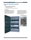
Terminal Blocks and Modules
The Crestron CLT terminal blocks and modules are considered a single
entity and must be used together. In field-assembled panels, they ship
separately to permit termination of the field wiring to the terminal block
prior to the installation of the module, and are mounted in any Crestron
Automation Enclosure (CAEN-series enclosures). The terminal block is
designed to terminate the circuit feed (HOT and NEUTRAL) and distribute
the controlled circuit (LOAD) to the fixture(s).
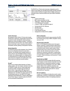
The module connects to the terminal block and performs dimming or
switching control of the loads, limited to 16A total per module. The unit
requires 120VAC 60 Hz, single phase input voltage.
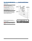
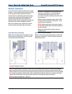
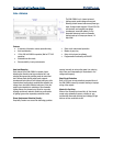
An oversize heat sink dissipates heat efficiently. The LEDs on the module
indicate communication to a Cresnet® network, input power to the module,
and output power to the load.
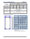
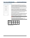
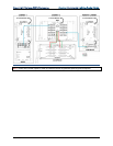
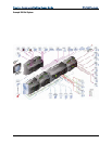
Terminal Blocks, Rails, and Labels (Inverted, right side units shown)
NOTES: When connecting dimming loads to an arc fault breaker, the load should not exceed 1000 watts per breaker.
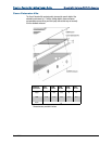
Each terminal block includes a terminal rail for mounting the terminal block in the enclosure. Terminal rails and blocks do not
occupy a module space within an enclosure.
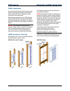
Terminal blocks are installed along the left side of single-wide enclosures and along the outside edges (left and right sides) of
enclosures. Modules are installed along the right side of single-wide enclosures and side-by-side in the center of enclosures.
When installing modules and terminal blocks in a double-wide enclosure, be sure to invert units on the right side so that they
can be properly wired.