


Crestron Commercial Lighting Design Guide Specifying a Lighting System
Doc. 4775A 8
Specifying a Lighting
System
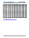
The Load Schedule
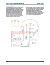
A lighting system design begins with a collection of
complete information. This includes a detailed floor plan
identifying all of the required elements. The first element
of design, the load schedule, is developed from the floor
plan. The load schedule lists the information on each
electrical load connected to every circuit in an electrical
panel. This primary source of information determines all
of the overall requirements:
Lighting types, required voltage and current,
dimmed or switched, fluorescent ballast types,
circuit number, normal or emergency, and
locations
The location and types of user interfaces used
(i.e., dimmers, switches, keypads, iLux™,
infiNET™, and touchpanels)
The control processor details (larger systems
should use a dedicated lighting control processor)
The window treatment details, which include
shade/blind motors and relay control (consult
the window treatment manufacturer for control
details).
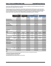
Required Load Schedule Items
1. Control zone: Controlled circuits that do not need
to be physically wired together, but always operate
in tandem. For example, perimeter lights, sconce
lights and overhead lights all operating together
2. Location of controlled lighting zone, relevant to
building site/drawings, floor designation, and
room name
3. Fixture and/or lamp type of controlled lighting
zone, including any information describing custom
fixtures, undetermined fixtures, dimmable
transformers or fluorescent ballasts, and circuit
breaker numbers. This information can also contain
the number assigned to the controlled circuit
4. Load type of the controlled lighting zone: load types
include incandescent, magnetic low voltage,
electronic low voltage, neon/cold cathode, HID,
dimmable/non-dimmable fluorescent ballast, ceiling
fans, and switched 3-wire motor circuits. This
information is especially important for selecting the
correct Crestron module power rating and type
5. Dimming requirement for the controlled lighting
zone (i.e. whether the lighting level of the
loads/fixtures needs to be ramped up/down or
simply switched on/off). Indicate: “Yes” for
Dimming, and “No” for Non-Dim
6. Emergency designation for the controlled lighting
zone (yes/no; i.e. when a load needs to be assigned
to a separate emergency power feed). These items
are assigned to their own separate dimmer, so they
can be fed with emergency power
7. Voltage rating for the controlled lighting zone tells
the designer the voltage of the electrical feeds
required for that zone, and hence the required
rating for the associated Crestron module.
8. Fixture wattage (watts or power rating per fixture)
with regard to the controlled lighting zone: this is
used to determine the number of fixtures that can
be powered per each Crestron Dimmer Module
channel, in order not to overload the dimmer
beyond its power rating
9. Quantity of fixtures for the controlled lighting zone:
this is useful, along with item #6, in calculating the
total power rating (watts) for that particular
controlled circuit (item #9)
10. Total wattage, or power rating, of the controlled
lighting zone: This is required in order to determine
the total number of Crestron Lighting Module
channels required for that particular zone,
especially if the load of the total number of fixtures
exceeds the rating of a single module channel
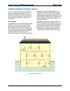
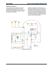
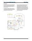
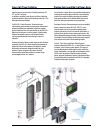
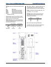
A riser diagram is requied for commercial lighting
projects. The simgle lin or sier diagram indicates
system components connected to individual circuits
in the system. Components connected to a
common circuit are shown as being connected to a
single line, regardless of the number of conductors
actually used. The number of conductors in each
wiring segment is usually indicated by right angle
marks across the single line at that point or by other
appropriate means
NOTE: National and local electrical codes and the
functionality of each user interface must be taken
into consideration. Always install electrical devices
according to the national Electrical Code (NEC), local
codes, and with safety in mind.