


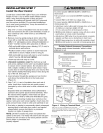
INSTALLING THE BRACKETS
Be sure power to the opener is disconnected. Install
and align the brackets so the sensors will face each
other across the garage door, with the beam no higher
than 6" (15 cm) above the floor. They may be installed in
one of three ways, as follows.
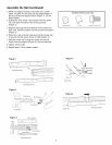
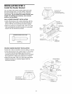
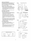
Garage door track installation (preferred):
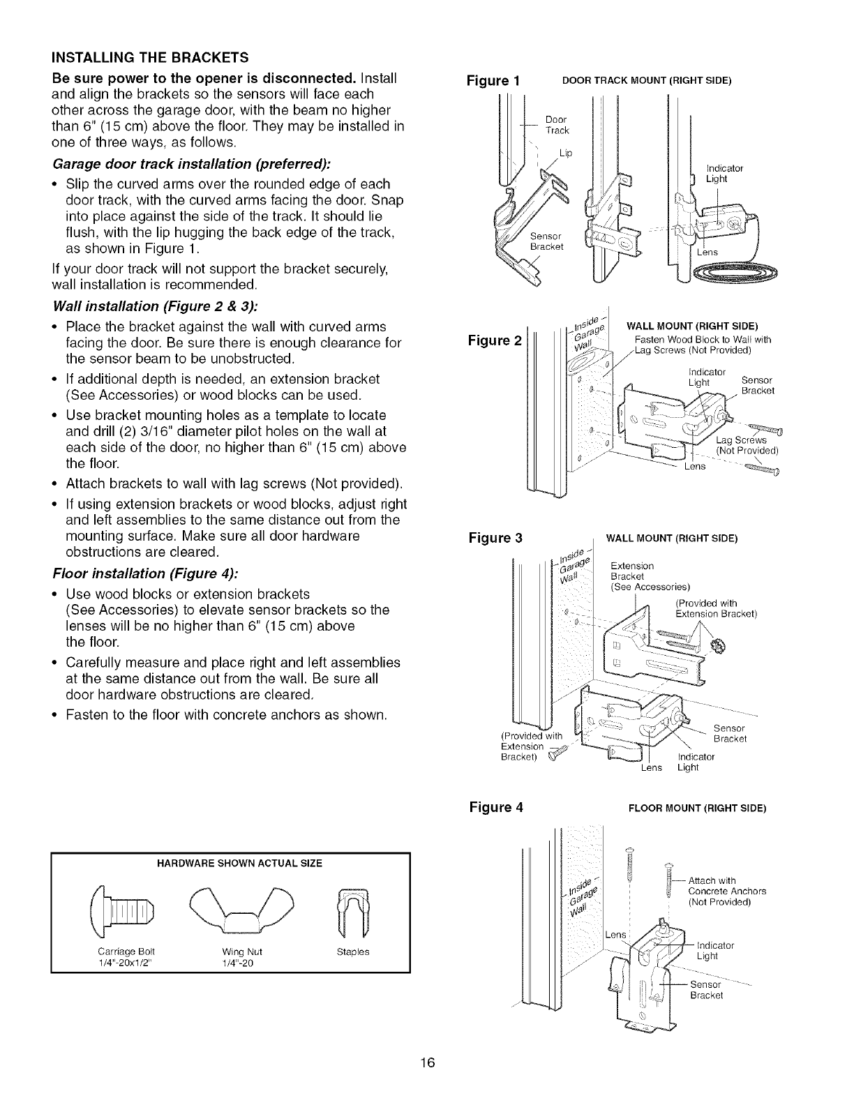
• Slip the curved arms over the rounded edge of each
door track, with the curved arms facing the door. Snap
into place against the side of the track. It should lie
flush, with the lip hugging the back edge of the track,
as shown in Figure 1.
If your door track will not support the bracket securely,
wall installation is recommended.
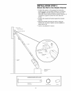
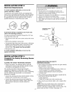
Wall installation (Figure 2 & 3):
• Place the bracket against the wall with curved arms
facing the door. Be sure there is enough clearance for
the sensor beam to be unobstructed.
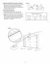
• If additional depth is needed, an extension bracket
(See Accessories) or wood blocks can be used.
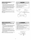
• Use bracket mounting holes as a template to locate
and drill (2) 3/16" diameter pilot holes on the wall at
each side of the door, no higher than 6" (15 cm) above
the floor.
• Attach brackets to wall with lag screws (Not provided).
• If using extension brackets or wood blocks, adjust right
and left assemblies to the same distance out from the
mounting surface. Make sure all door hardware
obstructions are cleared.
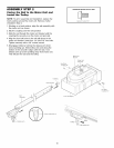
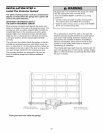
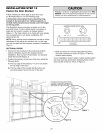
Floor installation (Figure 4):
• Use wood blocks or extension brackets
(See Accessories) to elevate sensor brackets so the
lenses will be no higher than 6" (15 cm) above
the floor.
• Carefully measure and place right and left assemblies
at the same distance out from the wall. Be sure all
door hardware obstructions are cleared.
• Fasten to the floor with concrete anchors as shown.
Figure
DOOR TRACK MOUNT (RIGHT SIDE)
Indicator
Light
Figure 2
WALL MOUNT (RIGHT SIDE)
Fasten Wood Block to Wall with
(Not Provided)
Indicator
Light Sensor
Bracket
Figure 3
WALL MOUNT (RIGHT SIDE)
Extension
Bracket
(See Accessories)
(Provided with
Extension Bracket)
(Provided with
Extension
Bracket)
Lens
Sensor
_\ Bracket
Indicator
Light
Figure 4 FLOOR MOUNT (RIGHT SIDE)
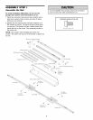
HARDWARE SHOWN ACTUAL SIZE
Carriage Bolt Wing Nut
1/4"-2 0x 1/2" 1/4"-2 0
StapJes
//
li_ Attach with
_i Concrete Anchors
(Not Provided)
Light
Bracket
16