


installation
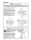
STE P 10 Connect Door Arm to Trolley
Follow only those instructions which apply to your door type
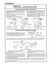
SECTIONAL DOOR INSTALLATION ONLY
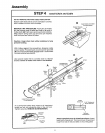
FIG, A. Make sure garage door is closed tight, Connect
straight door arm section to trolley with a clevis pin. Secure
with a ring or cotter pin fastener(if cotter pin is used, spread
to secure)
Fasten curved section to door bracket in the same way
FIG,, B. Bring arm sections together Find two pairs of holes
that line qp and join sections
Insert screws from straight arm side Select holes as far
apart as possible to increase door arm rigidity
A
Door
Bracket"
Clevis Pin-
B
_ _s Pin
Ring or
Cotter Pin
Fastener
/
!,_ _ Straight
Door ArmCurved
Door Arm
B_acke{
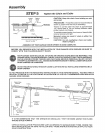
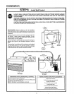
FIG. C. If holes do not line up as shown in FIG, B, cross door
arms inscissor fashion When one set of holes lines up, insert
screw and 'finger tighten' with a lock washer and nut
Pull the emergency release rope to disengage trolley.
Bring arm sections together and insert screw into second set
of holes Instalf lock washer and nut Tighten screws
Proceed to Step 1, Pg. 17. The trolley will re-engage
automatically when opener is operated.
-Rope
lency
Release Hand{e
"-_ Screws
5/16"q8 x 7/8-
C
Lock Washel
5/t6 '
Nu{
5/16"!8
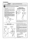
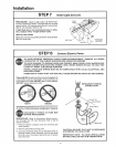
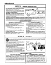
length With door closed, connect straight door arm sect ion
to door bracket with a clevis pin Secu re wit h a ring or cotter
pin fastener (if cotter pin is used, spread to secure )
ALL ONE-PIECE DOOR INSTALLATIONS
Ring or
ASSEMBLE DOORARMPROCEDURE:Connectstraight BDa°_re_ _°i!_nPin wL°l_ekrs 5/N_'!-s'8
" _ _ 5116"
and curved door arm sections together to longest possible ___-_" I/_
5/16,,.18 x 7/8" ----_ _
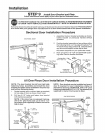
Before connecting door arm to trolley, limits of travel must be adjusted on one-piece doors, Limit adjustment
screws are located on left side panel of opener as shown in illustration on Pg. 1 7. Follow procedures below
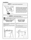
Fully Closed
Trolley
FuIly Open
Trolley
Door Arm ' i DOOrArm n o _r_n°°rt^r r_o_
. _.:Z[ .:::Z_*--" Connector Hole Co
: . L .
i Closed Open Door I)oor Arm LJ
[_ Door Door Arm
Bracket
ADJUSTMENT PROCEDURES
PROCEDURE- OPEN DOOR ADJUSTMENT
Decrease up limit. Turn UPlimit adjustment screw counter-
clockwise 4 complete turns
Press Wall Control button Trolley will travel to full open
Manually raise door to open position (parallel to floor) and lift
door arm to trolley The arm should touch trolley just in back
of door arm connector hole as shown in solid line drawing If
arm does not extend far enough, adjust limit furlher One fult
turn equals 2 inches of door travel
PROCEDURE - CLOSED DOOR ADJUSTMENT
Decrease down limit, Turn DOWN limit adjustment screw
clockwise 8 complete turns
Press Wall Control button Trolley will travel to full close
ManuaIly close door and lift door arm to trolley Arm should
touch trolley just ahead of door arm connector hole as shown
in dotted line drawing If arm is behind the connector hole,
adjust limit further One ful! turn pqual_ 2 inches of door
travel
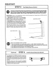
CON N ECT BOOR ARM TO TROLLEY: With door closed, join curved arm to connector hole in trolley with remaining clevis
pin Secure with ring or cotter pin fastener NOTE: It may be necessary to llft door slightly to make connection,,
Run opener throught a complete travel cycle If top of door has a sli0 _ , aownward' slant in lull open position, decrease UP
limits until door is parallel to floor
16