


CAUTION: Label all wires prior to disconnection when servicing
controls. Wiring errors can cause improper and
dangerous operation. Verify proper operation after
servicing.
WIRING INSTRUCTIONS –
GRAVITY WALL FURNACE
WARNING: Failure to locate the thermostat properly or to
wire the furnace correctly may result in continuous operation,
control damage or failure to operate. This can cause property
damage, personal injury, or loss of life.
Follow the instructions included with the thermostat. Locate the
thermostat approximately five (5) feet above the floor and four
feet (4’) from appliance. Always mount the thermostat on an
inside wall where it won’t be affected by heat or cold sources such
as direct sunlight, televisions, fireplaces, hidden hot or cold water
pipes, drafts, etc. The thermostat must never be installed in an
adjoining room where a door can be closed between the thermostat
and wall furnace. This wall furnace is equipped with a self
generating control system. Never connect to a 24 volt transformer
or to the household electrical system. Do not use more thermostat
wire than is included with the wall furnace. Do not run thermostat
wire in same stud space with vent. Conceal wire inside wall or
secure to wall with insulated staples that are included .
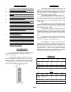
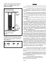
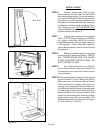
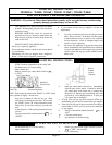
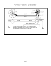
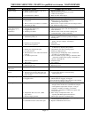
YOUR FURNACE MAY BE EQUIPPED WITH EITHER A
WALL THERMOSTAT (Figure 2) OR SNAP-BULB, BUILT-
IN THERMOSTAT (Figure 1) CONTROL. CHECK THE
CONTROL ASSEMBLY TO DETERMINE WHICH
WIRING EXAMPLE TO USE.
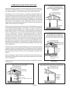
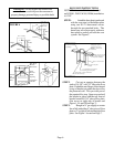
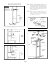
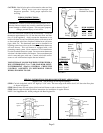
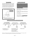
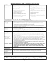
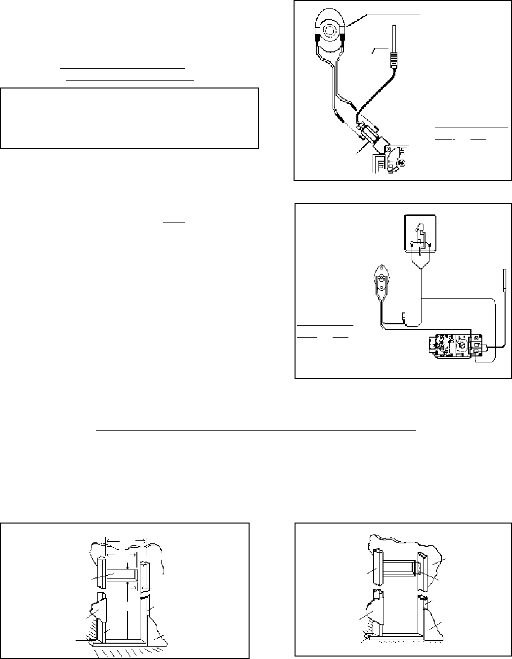
SPECIAL INSTRUCTIONS FOR REAR REGISTER KIT APPLICATION
(Figures 6 and 7 line drawings of rear register opening)
STEP 1.Cut hole in the back wall 8-1/4” high by 12-5/8” wide. The lower edge of the hole to be 45-3/4” above the floor plate
as shown in Figure 6.
STEP 2.Install frame for rear register in hole and nail frame to stud as shown in Figure 7.
STEP 3.Install rough-in header and follow instructions for installation of regular furnace.
NOTE: See Supplement No. 84504 packaged with Rear Register Kit.
Manual Reset
Blocked Flue Switch
Thermo-
couple
Gas
Valve
E.C.O.
Fitting
BULB MODELS
NAT. L.P.
W251F W252F
W351F W352F
W501F W502F
FIGURE 1
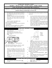
Thermostat
Manual
Reset
Blocked
Flue Switch
Wire
Nut
Pilot
Generator
Gas Valve
WALL
THERMOSTAT
MODELS
NAT. L.P.
W255F W256F
W355F W356F
W505F W506F
FIGURE 2
14-1/8
12-5/8”
Hole for back
register
Plaster
Stud
45-3/4”
Plaster
Opening 7/8” from
each stud
Stud
Plaster
FIG. 6 - ROUGH-IN DIMENSION FOR REAR REGISTER
Stud
Plaster
Plate
Plaster
Nail to stud
Stud
Plaster
FIG. 7 - PLACING FRAME FOR REAR REGISTER
Page 9
8-1/4”
Plate