


ROUGH-IN INSTRUCTIONS
NOTE: Maximum wall thickness for a dual
wall (W501, W502, W505, W506) installation
is 5-3/8”.
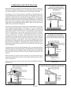
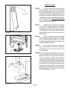
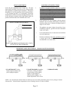
STEP 1. Attach the base plate (purchased
with the vent pipe) to the header plate
using two No. 8 sheet-metal screws
through the pre-punched holes. The
heater may not vent properly without a
base plate to anchor and seal the vent
system. See Figure C.
STEP 2. Cut out an opening between the
studs of 14-3/8” x 66-1/2” above the floor
plate. Embed the rear flange of the channel
on top of header into either the drywall or
the plastered wall. This provides part of
the required fire stop. Square up and nail
the header in place with the top front of
header located 65-3/4” above floor plate.
(See arrow on right side of header and
Figure 1, 5A and 5B on Page 7).
STEP 3. Rough in ½” gas supply on center
line of left stud either 4” above top of floor
plate or 4” to right of left stud through floor
plate. See Figure 1 located on Page 7.
Page 6
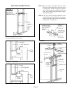
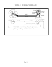
FIGURE C
Installation of B-W Gas
Vent for one story buildings
or for first floor of multi-
story buildings
Ceiling plate spacers to
center B-W gas vent in
stud space - nail securely
at both ends
Plate cut away for full
width of stud space to
provide ventilation
Studs on 16 inch centers
Sheet metal screw base plate
to header
Use manufacturer’s method of
fastening pipe to base plate
Header plate of vented wall furnace
(also acts as firestop)
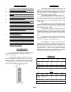
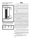
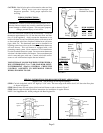
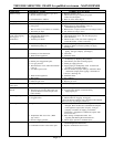
WARNING: Do not bypass the blocked flue
switch. To do so could expose the consumer to
property damage, personal injury or possible death.
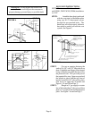
More than 10’
10’
Height above any
roof surface
within 10’
horizontally
2’ Min.
3’ Min.
Chimney
Ridge
10’ or Less
2’ Min.
3’ Min.
Chimney
Ridge
FIGURE A
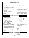
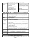
Man. Reset
Blocked
Flue Switch
Draft
Diverter
Relief
Opening
Switch/
Gas
Control
Wire
Reset
Button
FIGURE B FIGURE B-1
Combustion
Chamber