


ROUGH-IN INSTRUCTIONS
NOTE: For proper combustion, make sure units are
level, front to back and side to side.
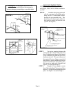
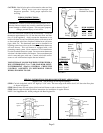
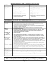
FIGURE 5A - DRY WALL
FIGURE 5B - PLASTER WALL
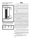
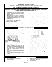
FIGURE 1
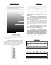
ROUGH-IN
DIMENSIONS
Dry-Wall
B-W Type Vent
Front
Panel
Screw
Plaster
Ground
Plaster
B-W Type Vent
Screw
Front
Panel
Plaster
Ground
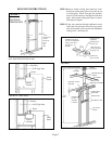
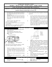
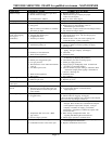
STEP 4.Remove double ceiling plate between studs.
Install one ceiling plate spacer across the cut out
in ceiling plate. Install vent pipe into position,
be sure to lock bottom of vent pipe into the base
plate. Nail second ceiling plate spacer in place.
(See Figure C, Page 6).
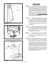
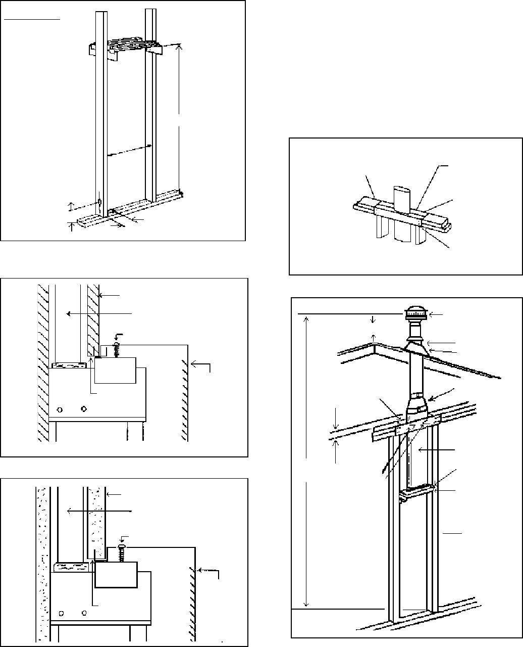
STEP 5.If the vent continues through additional stories
within the 2x4-stud space, then fire-stop-spacers
must be installed at the second and subsequent
ceiling levels. See Figure D.
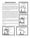
FIGURE D
Installation of B-W gas
vent for each subsequent
ceiling or floor level
of multi-story
buildings
Firestop spacers
supplied by
manufacturer of
B-W gas vent
Plate cut away to
provide passage of
B-W gas vent
Nail firestop
spacer securely
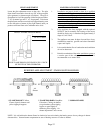
VENT INSTALLATION
2 FT. MIN.
LISTED
VENT TOP
STORM COLLAR
ROOF
FLASHING
OVAL TO
ROUND ADAPTER
CEILING PLATE
SPACERS
12 FT.
MIN.
LISTED “BW”
VENT PIPE
BASE PLATE
HEADER PLATE
2 X 4 WALL
STUDS
CEILING
PLATE
SPACER
LANCES
Page 7
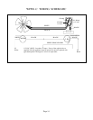
FIGURE 2 - VENT INSTALLATION
*65-3/4”
* This
measurement
must be
taken from
top of
floor
plate
4”
4”
14-1/4”
Min.
14-1/2” Max.