


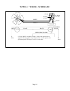

VENTING
This appliance must be properly connected to a venting
system.
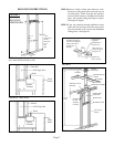
Consult local ordinances governing venting. Install only
UL listed type BW 4” oval gas vent. When the vent enters the
attic, a listed type B-1 round flue pipe may be used. See Figure
2, Page 7.
Vent pipe must connect to the wall furnace header plate
with a “B” vent base plate and terminate with a cap at a point at
least 12 foot above the bottom of the wall furnace, two feet
above any obstacle within a 10 foot radius, and at least 3 foot
above the roof.
Provisions must be made for adequate combustion and
ventilation air.
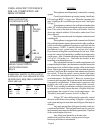
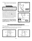
This appliance is equipped with a manual reset blocked
flue switch designed to protect against a blocked flue condition,
which would cause combustion products to spill back into the
living quarters. NOTE: A partially blocked, inadequate, or
disconnected vent system may not activate the switch.
Discoloration of the grille is an indication of a bad vent. If this
occurs, the vent can be checked by a qualified serviceman using
a draft gauge. After 15 minutes the gauge should read between
-.02 up to -.04 inches w.c. Vent must be checked at the
beginning of each heating season.
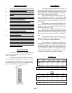
The switch when activated on a bulb control burner will
extinguish the pilot flame, on a thermostat controlled burner, the
thermostat circuit will be broken, turning off the main burner
flame. Before the heater can be relit, the reset button must be
activated. See Figure B for location of the manual reset blocked
flue switch. To reset the switch, insert a slender rigid object
(i.e. screwdriver) through the front panel louvers and push the
reset button down. See Figure B-1. However, you may have
to remove the front panel, then reset the switch and reinstall the
front panel to relight heater. If homeowner experiences this
problem, the vent system must be checked and corrected.
NOTE: A pre-existing vent that has worked for years may not
be adequate for todays design because of higher efficiency
requirements that result in lower stack temperatures. See
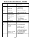
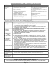
“Possible Causes and Corrective Action” on Page 16.
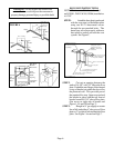
All type “B” vents shall extend in a generally vertical
direction with offsets not exceeding 45 degrees, except that a
vent system having not more than one 60 degree offset may be
allowed.
Any angle greater than 45 degrees from the vertical is
considered horizontal. The total horizontal run of a vent plus
the horizontal vent connector shall be not greater than 75 percent
of the vertical height of the vent.
Any offsets used should be as far above the
drafthood as possible to allow a venting action to begin
before any restriction is encountered.
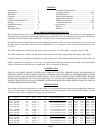
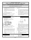
BASED ON 4,000 BTU OF TOTAL INPUT
RATING OF ALL GAS APPLIANCES, THE
HEATER ONLY REQUIRES A MINIMUM
FREE AREA OF:
Page 5
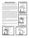
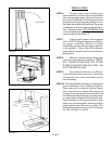
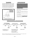
USING ADJACENT STUD SPACE
FOR ALL COMBUSTION AIR
FROM OUTSIDE
HOLES CONNECTING
TO VENTILATED ATTIC
CEILING
PLATE
AIR
GRILLE
FLOOR
PLATE
HOLES CONNECTING TO
VENTILATED CRAWL
SPACE
SQUARE HOLE SQUARE
BTU IN. SIZE = IN.
25,000 6.25 1” .785
35,000 8.75 1.5” 1.76
50,000 12.50 2” 3.14