


1”
11”
2”
SAFETY RULES
A) The wall furnace should be located near the center of
the house for best heat distribution.
B) Due to high temperatures, the appliance should be
located out of traffic and away from furniture and
draperies.
C)
Children and adults should be alerted to the hazards
of high surface temperature and should stay away to
avoid burns or clothing ignition.
D) Young children should be carefully supervised when
they are in the same room as the appliance.
E) Do not place clothing or other flammable material on
or near the appliance. Precautions should be taken
so as not to place furniture, drapes, or other articles
directly in front of grille or lower access door that
would obstruct air openings as proper air flow is
critical to proper operation of unit.
F) Any safety screen guard or casing front removed for
servicing an appliance must be replaced prior to
operating the appliance.
G) If the area where the appliance is to be installed
contains carpeting, tile or combustible materials, other
than wood flooring, the appliance shall be installed
on a metal plate, a wood panel or other non-
combustible materials. The use of ceramic or quarry
tile is acceptable and will provide a surface that is
easily cleaned. This material is to extend the full width
and depth of the appliance.
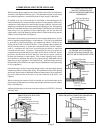
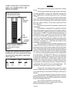
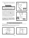
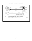
CLEARANCES
As viewed from front of heater, the minimum clearance
from cabinet to combustible construction: Side Wall – 1”;
Floor – 2”; Ceiling – 11”.
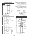
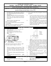
with clips provided. DO NOT KINK the connecting
tubing. Do not bend the capillary bulb.
The normal manifold pressure should be 3.5”
w.c. on Natural Gas and 10” w.c. on L.P. Gas. The
maximum inlet pressure in the gas supply pipe should
never exceed 14” w.c. on L.P. Gas or 7.0” w.c. on
Natural Gas.
The appliance and its individual shutoff valve
must be disconnected from the gas supply piping system
during any pressure testing of that system at test
pressures in excess of ½ psig.
The appliance must be isolated from the gas
supply piping system by closing its individual manual
shutoff valve during any pressure testing of the gas supply
piping system at test pressures equal to or less than ½
psig.
The minimum inlet pressure in the gas supply
pipe should be 5.0” w.c. on Natural Gas or 11” w.c. on
L.P. Gas, “for purpose of input adjustment”.
The appliance is orificed at the factory for
elevations up to 2,000 feet. If installed above 2,000 feet,
the BTU input must be reduced 4% per 1,000 feet. See
the following orifice chart for the proper orifice for a
specific elevation. A blank orifice is shipped in the high
altitude kit which will have to be drilled to correct size
by installer, gas supplier or qualified serviceman.
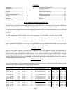
NATURAL GAS
Model 0 to 2,000 - 4,000 - 6,000 - 8,000 –
No. 2,000’ 4,000’ 6,000’ 8,000’ 10,000’
W251F 43 44 45 47 48
W255F 43 44 45 47 48
W351F 36 38 40 41 43
W355F 36 38 40 41 43
ORDER KIT #49820 45-1 HIGH ALTITUDE KIT
W501F 43 44 45 47 48
W505F 43 44 45 47 48
ORDER KIT #49850 2287-2 HIGH ALTITUDE KIT
L.P. GAS
Model 0 to 2,000 - 4,000 - 6,000 - 8,000 –
No. 2,000’ 4,000’ 6,000’ 8,000’ 10,000’
W252F 1.45mm 54 54 55 55
W256F 1.45mm 54 54 55 55
W352F 52 52 52 53 54
W356F 52 52 52 53 54
ORDER KIT #49820 45-1 HIGH ALTITUDE KIT
W502F 1.45mm 54 54 55 55
W506F 1.45mm 54 54 55 55
ORDER KIT #49850 2287-2 HIGH ALTITUDE KIT
Page 3
In selecting a location for installation it is necessary
to provide adequate accessibility clearances for servicing
and proper operation. This appliance must not be connected
to a chimney flue that serves to vent a solid-fuel burning
(wood or coal) appliance, or a multi-vent system.
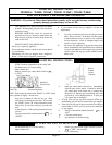
CONTROLS
All controls are preassembled at the factory. If
integral snap-bulb type thermostat is used, make sure
that sensing bulb is located on the bottom of gas valve