


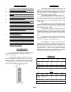
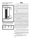
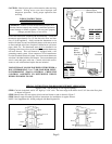

B-W VENT
FIGURE 3
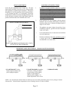
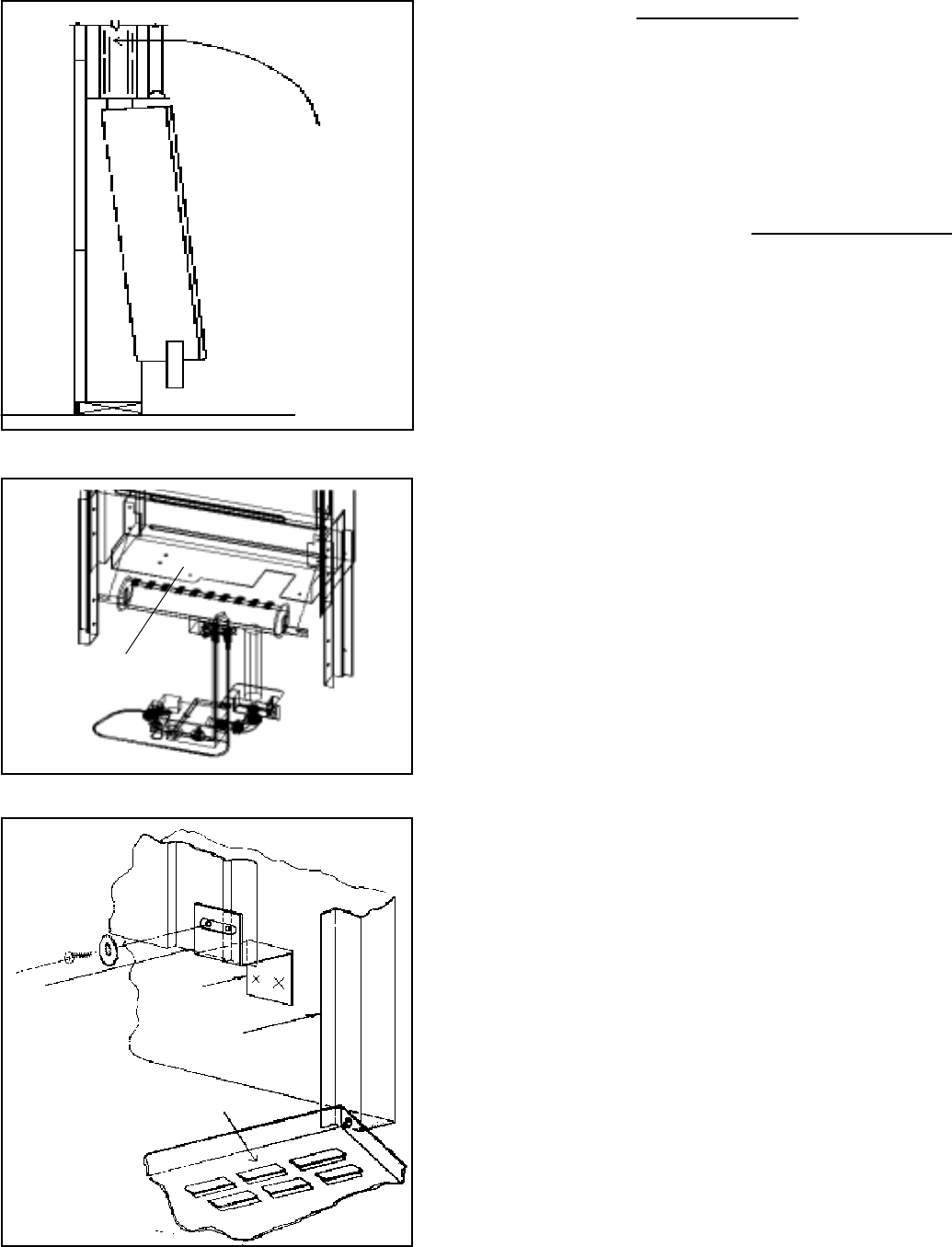
Casing
“Z Bracket
Front Panel
Front
Panel
Door
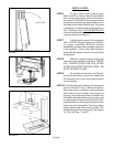
FIGURE 5C
INSTALLATION
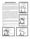
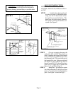
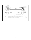
STEP 6. To place furnace into position, grasp
furnace and lift so furnace flue vent and header
plate vent opening engage. Do not use burner or
gas control to lift heater. Lift furnace upward and
swing bottom into wall opening until legs rest on
floor plate and are flush to finished wall. For proper
combustion, level heater front to back and side to
side. Nail legs to studs. DO NOT BEND LEGS
as this will put the entire unit into a bind and cause
expansion noises (See Figure 3).
STEP 7. A drip leg and a manual valve equipped
with a 1/8 N.P.T. plugged tapping accessible for
test gauge connection should be installed
immediately upstream of the gas supply connection
to the appliance. Some codes and ordinances
require that the manual valve be located outside
the appliance.
STEP 8. Make gas connection using connector the
same size as gas connection of furnace. CHECK
ALL CONNECTIONS FOR GAS LEAKS
WITH LEAK DETECTOR SOLUTION. DO
NOT USE OPEN FLAME.
STEP 9. For wall thermostat units, see “Wiring”
section for thermostat connections. Make sure
all connections are correct and connector stems
are not touching.
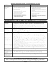
STEP 10. To fasten front panel to furnace, be sure exposed
portion of header is free of debris and plaster.
Place outer panel over furnace with top of panel
about one inch above header and centered in
opening. Keep front panel flush to finished wall
and slide down until rear flange of top outer panel
is wedged tight with header and flush with wall.
Open bottom door of front panel and place sheet
metal screw into locking latch. Secure top of front
panel to header plate with screw provided. This
will hold front panel securely to wall. See Figures
5A, 5B, (See Page 7), and 5C.
Page 8
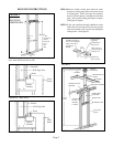
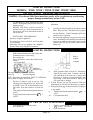
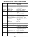
BURNER
SHELF
FIGURE 4