


STEP 4.
a)
b)
c)
d)
e)
t)
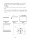
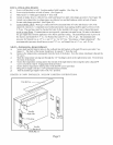
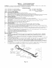
INSTALLING HEATER
Screw wall brackets to wall. Location marked with template. (See Step la)
Screw trim kit brackets to back of heater. (See Figure 9).
Slide heater to within approximately 5" from wall.
Attach air intake hose to collector box outlet and burner box inlet with clamps provided. (See Figure 10).
Attach vent exhaust tube to exhaust pipe on collector box and draft inducer outlet on back of heater.
Secure with clamps provided. (See Figure 10).
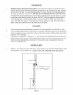
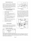
GAS CONNECTION. Make gas connection between manual shut offvalve and furnace valve with
approved connectors. Compounds used on threaded joints of gas piping shall be approved for use with
L.R gas. The gas lines must be checked for leaks by the installer with soapy water or liquid detergent,
never an open flame. If connections are not exposed, a pressure test must be run. Be sure to disconnect
the gas supply line from the appliance valve before pressure testing. The manifold pressure is pre-set at
the factory and should be 3.5" w.c. for Natural Gas and 10" w.c. for L.R gas. The minimum inlet
pressure for Natural Gas is 4.5" w.c. and 11" w.c. for L.R Gas, "for purpose of input adjustment". The
maximum inlet pressure should never exceed 7.0" w.c. on Natural Gas or 14" w.c. on L.R Gas.
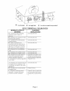
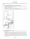
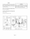
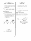
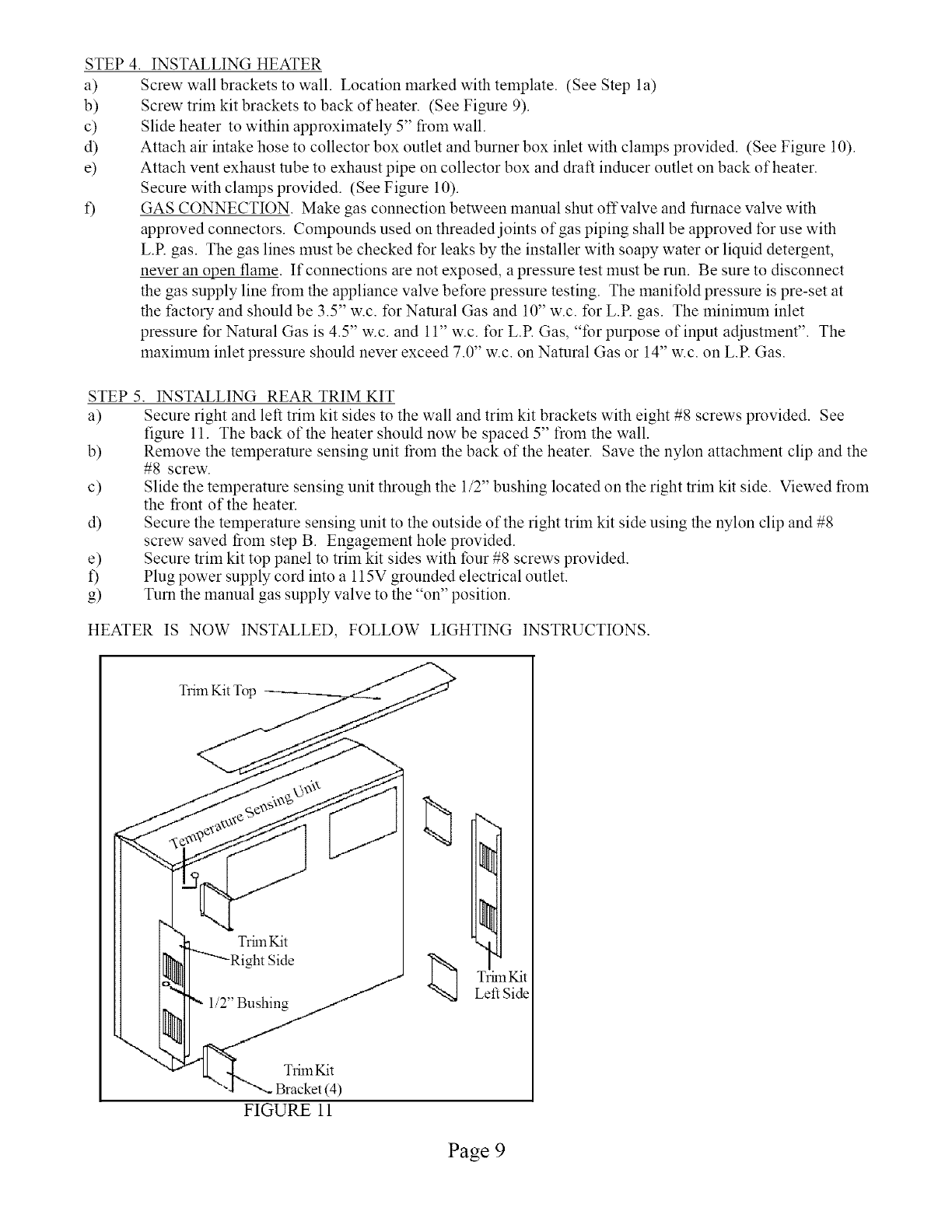
STEP 5. INSTALLING REAR TRIM KIT
a) Secure right and left trim kit sides to the wall and trim kit brackets with eight #8 screws provided. See
figure 11. The back of the heater should now be spaced 5" from the wall.
b) Remove the temperature sensing unit from the back of the heater. Save the nylon attachment clip and the
#8 screw.
c) Slide the temperature sensing unit through the 1/2" bushing located on the right trim kit side. Viewed from
the front of the heater.
d) Secure the temperature sensing unit to the outside of the right trim kit side using the nylon clip and #8
screw saved ti'om step B. Engagement hole provided.
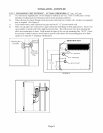
e) Secure trim kit top panel to trim kit sides with tour #8 screws provided.
f) Plug power supply cord into a 115V grounded electrical outlet.
g) Turn the manual gas supply valve to the "on" position.
HEATER IS NOW INSTALLED, FOLLOW LIGHTING INSTRUCTIONS.
Trim Kit
(4)
FIGURE 11
Trim Kit
Left Side
Page 9