


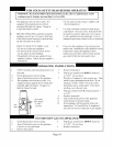
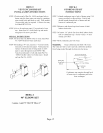
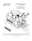
TROUBLE SHOOTING CONTROL BOARD
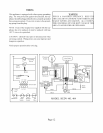
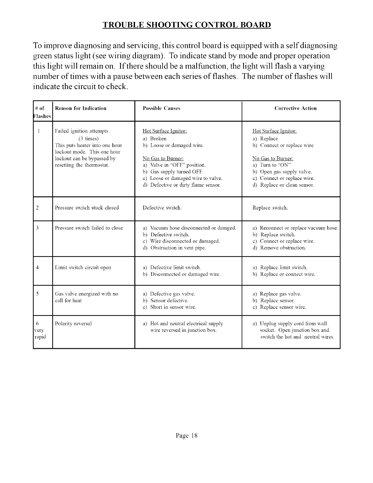
To improve diagnosing and servicing, this control board is equipped with a self diagnosing
green status light (see wiring diagram). To indicate stand by mode and proper operation
this light will remain on. If there should be a malfunction, the light will flash a varying
number of times with a pause between each series of flashes. The number of flashes will
indicate the circuit to check.
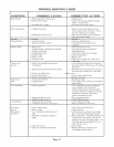
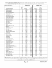
# of Possible Causes Corrective Action
Flashes
1
6
very
rapid
Reason for Indication
Failed ignition attempts
(3 times)
This puts heater into one hour
lockout mode. This one hour
lockout can be bypassed by
resetting the thermostat.
Pressure switch stuck closed
Pressure switch failed to close a)
b)
c)
d)
Limit switch circuit open a)
b)
Gas valve energized with no a)
call for heat b)
c)
Polarity reversal a)
Hot Surface I_nitor:
a) Broken
b) Loose or damaged wire.
No Gas to Burner:
a) Valve in "OFF" position.
b) Gas supply turued OFF.
c) Loose or damaged wire to valve.
d) Defective or dirty flame sensor.
Defective switch.
Vacuum hose disconnected or damged.
Defective switch.
Wire disconnected or damaged.
Obstruction in vent pipe.
Defective limit switch.
Disconnected or damaged wire.
Defective gas valve.
Sensor defective.
Short in sensor wire.
Hot and neutral electrical supply
wire reversed in junction box.
Hot Surface I_nitor:
a) Replace
b) Connect or replace wire
No Gas to Burner:
a) Tum to "ON"
b) Open gas supply valve.
c) Connect or replace wire.
d) Replace or clean sensor.
Replace switch.
a) Reconnect or replace vacuum hose.
b) Replace switch.
c) Connect or replace wire.
d) Remove obstruction.
a) Replace limit switch.
b) Replace or connect wire.
a) Replace gas valve.
b) Replace sensor.
c) Replace sensor wire.
a) Unplug supply cord from wall
socket. Open junction box and
switch the hot and neutral wires.
Page 18