


INSTALLATION
Failure to follow these instructions carefully could result in poor performance_ property damage, personal injury_ or
death.
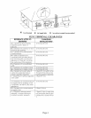
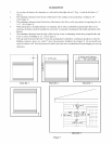
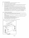
STEP 1. LOCATE VENT OPENING (Requires 3-1/2" diameter wall opening)
a) Select area on wall where heater will be installed. Using template (packed with heater) mark shaded area
b)
c)
d)
e)
where hole can be cut and to locate the wall brackets.
Locate studs on each side of this area.
Mark location for 3-1/2" diameter hole between studs. Hole should be of[;et to miss studs. (See Figure 6).
Check outside wall at this location for proper clearances around vent cap.
Cut vent openings into both the inside and outside walls, being sure to maintain level across both openings.
I
L_, /"
I I
I
I
I
I
I ..-- Wall
J!Studs
[ 16" O.C.
I
Template
t
I7
t t
II
tt
t t
tt Shaded
Area
I I I
FIGURE 6
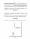
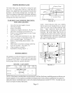
1/8" N.P.T. Plu_
for Pressure Gauge
Manual Shut
OffValve
I
I I
Gas Supply
Inlet
(hound Joint
Union
'(761rnn)Min.
FIGURE 7
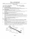
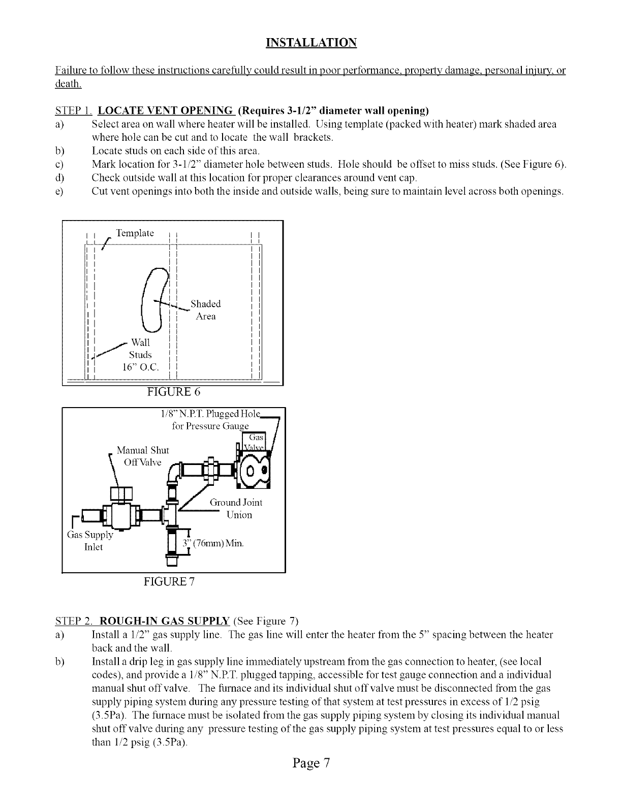
STEP 2. ROUGH-IN GAS SUPPLY (See Figure 7)
a) Install a 1/2" gas supply line. The gas line will enter the heater from the 5" spacing between the heater
back and the wall.
b) Install a drip leg in gas supply line immediately upstream from the gas connection to heater, (see local
codes), and provide a 1/8" N.RT. plugged tapping, accessible for test gauge connection and a individual
manual shut offvalve. The furnace and its individual shut offvalve must be disconnected from the gas
supply piping system during any pressure testing of that system at test pressures in excess of 1/2 psig
(3.5Pa). The furnace must be isolated from the gas supply piping system by closing its individual manual
shut off valve during any pressure testing of the gas supply piping system at test pressures equal to or less
than 1/2 psig (3.5Pa).
Page 7