


CONNECTING THE VENT - Continued
®
@
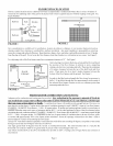
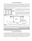
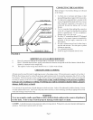
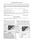
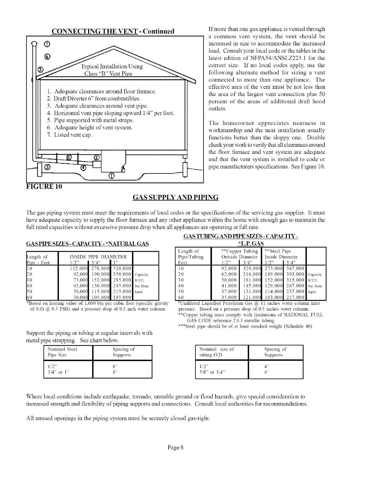
)ical Installation Using
Class "B" Vent Pipe
1. Adequate clearances around floor furnace.
2. Draft Diverter 6" from combustibles.
3. Adequate clearances around vent pipe.
4. Horizontal vent pipe sloping upward 1/4" per t\)ot.
5. Pipe supported with metal straps.
6. Adequate height of vent system.
7. Listed vent cap.
@
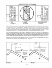
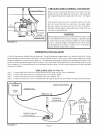
If more than one gas appliance is vented through
a common vent system, the vent should be
increased in size to accommodate the increased
load. Consult your local code or the tables in the
latest edition of NFPA54/ANSI.Z223.1 t\_r the
correct size. If no local codes apply, use the
following alternate method for sizing a vent
connected to more than one appliance. The
effective area of the vent must be not less than
the area of the largest vent connection plus 50
percent of the areas of additional draft hood
outlets.
The homeowner appreciates neatness in
workmanship and the neat installation usually
functions better than the sloppy one. Double
check your work to verify that all clearances around
the floor furnace and vent system are adequate
and that the vent system is installed to code or
pipe manuthcturers specifications. SeeFigure 10.
FIGURE 10
GAS SUPPLY AND PIPING
The gas piping system must meet the requirements of local codes or the specifications of the selwicing gas supplier. It must
have adequate capacity to supply the floor furnace and any other appliance within the home with enough gas to maintain the
full rated capacities without excessive pressure drop when all appliances are operating at full rate.
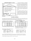
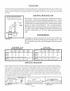
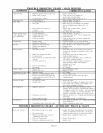
GAS TUBING AND PIPE SIZES - CAPA(ITY-
GAS PIPE SIZES - CAPACITY- *NATURAL GAS
_ength of
_ipe - Feet
0
_.0
_0
_0
_0
_0
INSIDE PIPE DIAMETER
1/2" I 3/4" | 1"
132,000 278,000 520,000
92.000 190,000 350,000
73.000 152,000 285,000
63.000 130,000 245,000
56.000 115,000 215,000
50.000 105,000 195,000
Capacity
BTU
Per Hour
Input
*Based on heating value of 1.000 btu per cubic foot (specific gravity
of 0.6) (a 0.5 PSIG and a pressure drop of 0.3 inch water colunm.
Support the piping or tubing at re_lar intelwals with
metal pipe strapping. See chart below.
Nominal Steel Spacing of
Pipe Size Supports
1/2" 6'
3/4" or 1" 8'
Length of
Pipe/Tubing
Feet
10
2O
3O
4O
50
60
*L.E GAS
**Copper Tubing
Outside Diameter
1/2" 3/4"
92,000 329.000
62,000 216,000
50,000 181,000
41,000 145,000
37,000 131,000
35,000 121,000
**Steel Pipe
Inside Diameter
1/2" 3/4"
275.000 567.000
189.000 393,000 Capacity
152,000 315.000 BTU
129,000 267.000 PerHour
114,000 237,000 Inpm
103,000 217,000
*Undiluted Liquefied Petroleum Gas @ 11 inches water column inlet
pressure. Based on a pressare drop of 05 inches water colunm.
**Copper tubing must comply with limitations of NATIONAL FUEL
GAS (;ODE reference 2.6.3 metallic tubing.
***Steel pipe should be of at least standard weight (Schedule 40).
Nominal size of
tubing O.D.
1/:2"
58" or 3/4"
Spacing of
Supports
4'
6'
Where local conditions include earthquake, tornado, unstable ground or flood hazards, give special consideration to
increased strength and flexibility of piping supports and connections. Consult local authorities f\3rrecommendations.
All unused openings in the piping system must be securely closed gas-tight.
Page 8