


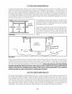
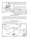

VENT SYSTEM
After the floor furnace has been burning t\3rfive minutes, hold a match or candle under the draft hood at the air intake area. If
the vent system is working properly, the flame will be pulled into the air inlet of the draft hood. If the vent system is not working
properly, turn the floor furnace off immediately and refer to the installation instructions or local code for proper installation
procedure.
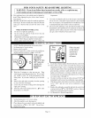
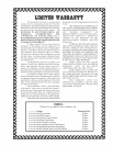
PILOT FLAME ADJUSTMENT
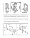
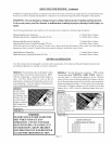
Pilot flame should envelop 3/8 to
1/2 inch of the tip of the generator.
, _" i l
I I
4'
3/8 to
€ 1/2"
FIGURE 17
ADJUSTING THE PILOT FLAME
Refer to Figure 17 for the correct size pilot flmne. If adjustment is necessary,
refer to Figure 12 for the location of the pilot adjustment screw. Using a
standard screwdriver, remove the pilot adjustment screw cover. Insert a
small screwdriver into the pilot adjusnnent screw and turn clockwise _ to
decrease the flame or counterclockwise _ to increase the flame.
If the flame is too low, the safety pilot may cause all of the gas to be cut
off. NOTE: The gas supply to the pilot is unregulated. When line pressure
exceeds 7" Natural Gas, or 11" L.R Gas, a pilot adjustment must be
made.
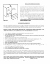
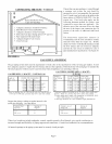
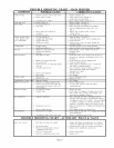
BURNER ORIFICE
This appliance is orificed atthe factory for elevations up to 2,000 feet. If
installed above 2,000 feet, the BTU input must be reduced 4% per 1,000
feet. See the following orifice chart for the proper orifice for a specific
elevation.
NATURAL GAS
SPE( IFI(_ ELEVATIONS
Vlodel No. 0 to 2,000 - 4,000 -
2,000' 4.000' 6.000'
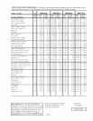
)0N30A 38 41 42
)0N50A 30 31 31
)0N65A 26 28 29
:)RDER KIT #49800 44-i HIGH ALTITUDE KIT
)0N75A 33 36 37 38
DRDER KIT #49850
6,000- 8,000
8,000' 10,000'
43 44
32 35
30 30
41
2287-2 HIGH ALTITUDE KIT
L.P. GAS
SPE(IFI(;ELEVATIONS
Model No. 0to 2,000- 4,000- 6,000- 8,000
2,000' 4,000' 6,000' 8,000' 10,000'
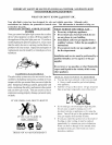
90P30A 1/16 53 53 54 54
90P50A 47 49 49 50 51
90P65A 43 44 45 47 48
ORDER KIT #49800 44-1 HIGH ALTITUDE KIT
90P75A 51 52 52 53 54
ORDER KIT #49850 2287-2 HIGH ALTITUDE KIT
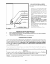
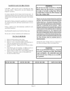
ADJUSTING THE BURNER
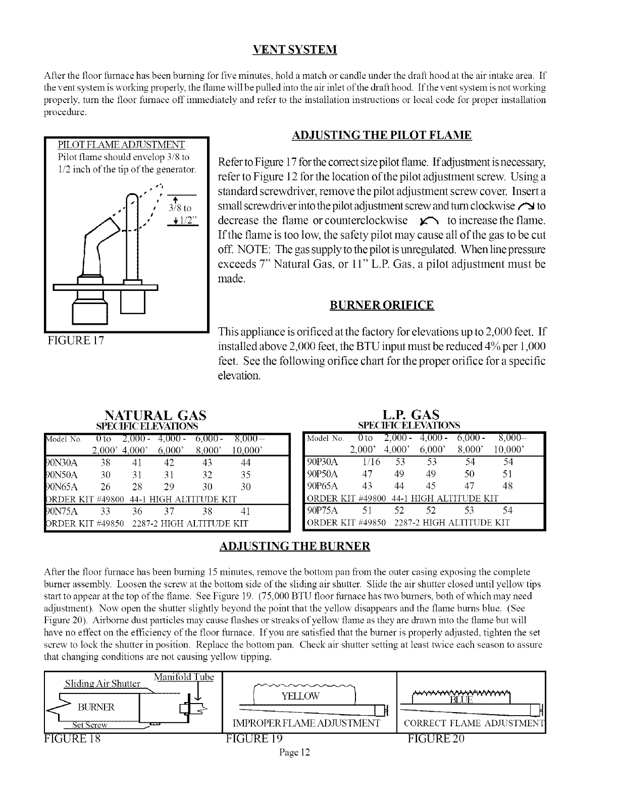
After the floor furnace has been burning 15 minutes, remove the bottom pan fiom the outer casing exposing the complete
burner asselnbty. Loosen the screw at the bottom side of the sliding air shutter. Slide the air shutter closed until yellow tips
start to appear at the top of the flame. See Figure 19. (75,000 BTU floor furnace has two burners, both of which may need
adjustment). Now open the shutter slightly beyond the point that the yellow disappears and the flame burns blue. (See
Figure 20). Airborne dust particles may cause flashes or streaks of yellow flame as they are drawn into the flame but will
have no effect on the efficiency of the floor furnace. If you are satisfied that the burner is properly adjusted, tighten the set
screw to lock the shutter in position. Replace the bottom pan. Check air shutter setting at least twice each season to assure
that changing conditions are not causing yellow tipping.
Manifold Tube
Sliding Air Shutter ",,
4;
Set Screw _
FIGURE 18
IAt
IMPROPER FLAME ADJUSTMENT
FIGURE 19
Page 12
ADJ STM
FIGURE 20