


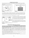
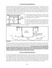
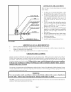
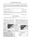

FLOOR FURNACE LOCATION
Choose a central location such as a hallway but where occupant traffic is minimal and where there is at least 18 inches of
room from two adjoining sides of the grill to the nearest wall so that occupants may pass without stepping on the gill. See
Figure Number 1.
Bedroom
Bath_ Kitchen
Vent Pipe |
I
Living Room ]
M
,) WALL <
't
8"Minilntun
Bedroom
FIGURE 1 FIGURE 2
Give consideration to available air for combustion, location in relation to chimney or vent system, thermostat location,
clearance under floor, clearance to combustibles, and heat circulation. Any open foundation is unacceptable as wind can
cause pilot outage and reduced efficiency. Keep furniture, drapes, doors, and other combustible materials at least 12inches
from the edge of the gill. Never locate the floor furnace closer than 8 inches to a walt and never in a corner. See Figure 2.
Two adjoining sides of the floor furnace must have a minimum clearance of 18". See Figure 1.
FLOOR
_ JOIST
FLOOR
FURNACE
FLOOR
.d_
Ground _,
Level 6" Minimum
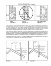
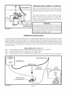
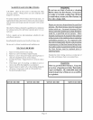
After selecting a location in the home, go beneath the floor and check
the position of the floor furnace in relation to joists, supporting
columns, electric wires, water pipes and walts. There must be aminhnum
of 6 inches clearance between the top of the draft hood and floor
joists. There must also be at least 6 inches clearance between the
bottom of the floor furuace and the ground. See Figure 3.
In order to find the location beneath the floor it may be necessary to
drill a 1/16 inch hole through the floor approximately in the center of
the selected floor furnace location to use as a reference point when
measuring under the floor.
FIGURE 3
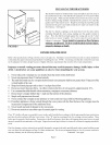
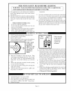
FRESH AIR FOR COMBUSTION AND VENTING
Adequate air for combustion and venting must be provided. Any reduction in the necessary amount of fresh air
can result in an oxygen starved flame that emits Carbon Monoxide (C.O.) an odorless, colorless gas
that can cause serious injury or death. A ventilated crawl space will usually provide enough tiesh air. However, you
must check to see that there is 1 square inch of free area of ventilation opening for each 1,000 BTU's input of your floor furnace.
EXAMPLE: 50,000 BTU floor furnace 1,000 50 square inches. If another gas burning appliance such as a water heater is
installed within the same crawl space or basement, add the B.T.U.'s of the other appliance to those of the floor furnace before
calculating the total ventilation needed. EXAMPLE: 50,000 B.T.U. floor furnace plus 40,000 B.T.U. water heater equals 90,000
B.T.U. ÷ 1,000 90 square inches. To compensate tbr the loss of square inches of ventilation due to the use of louvers, gills,
or screens add approximately 50% to the square inches calculated. Screen all openings with mesh not less than ¼ inch to
prevent animals or insects from entering the crawl space.
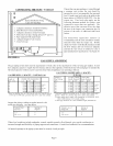
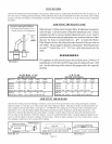
All type "B" vents shall extend in a generally vertical direction with oft;ets not exceeding 45 degees, except that a vent system
having not more than one 60 degee oft;et may be allowed.
Any angle geater than 45 degees t'rom the vertical is considered horizontal. The total horizontal run of a vent plus the
horizontal vent connector shall be not geater than 75 percent of the vertical height of the vent.
Any ofl;ets used should be as far above the drafthood as possible to allow a venting action to begin before any restriction is
encountered.
Page 4