


Pilot
Adiustlnen
®
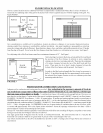
FIGURE 12
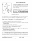
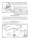
CHECKING THE GAS PIPING- CONTINUED
When you have determined that there are no leaks in the gas
piping system you may purge the system of air. Disconnect the
pilot supply tubing from the right side of the valve. See Fimlre
12.
Turn the knob on the gas valve to the pilot position. Press the
knob down and hold until you smell gas at the pilot supply
opening. Release the knob and turn it to the off position.
Reconnect the pilot supply tubing and check t\_rleaks with soap
and water or liquid detergent.
WARNING
When purging gas piping, the area around the floor furnace must
be welt ventilated to allow any gas to dissipate. Liquid Petroleum
(L.R) Gas is heavier than air and may puddle in low places under
the floor. Check thoroughly to determine that no gas is present
bel\_re lighting the floor furnace. Failure to do so could result in
property damage, bodily injury or death.
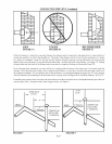
THERMOSTAT INSTALLATION
Follow the instructions included with the thermostat. Locate the thermostat approximately five feet above the floor. Always
mount the thermostat on an inside wall where it won't be affected by heat or cold sources such as direct sunlight, televisions,
fireplaces, hidden hot or cold water pipe, drafts, etc. The thermostat must never be installed in an adjoining room where a door
can be closed between the thermostat and floor furnace. This floor furnace is equipped with a self-generating control system.
Never connect to a 24-volt transl\_rmer or to the household electric system. Do not use more thermostat wire than is included
with the floor furnace.
Step 1.
Step 2.
Step 3.
Step 4.
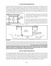
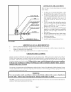
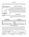
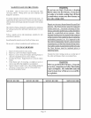
WIRE AS INDICATED: (See Figure 13)
Connect black limit switch wire to black thermostat wire using wire nut. (Nut not furnished).
Connect white thermostat wire to terminal on gas valve marked "TH PP".
Connect white limit switch wire to terminal on gas valve marked "TH".
Connect the thermostat wires to the thermostat following the instructions provided by the thermostat manufacturer.
THERMOSTAT
WIRE NUT
LIMIT SWITCH WIRES
TERMINAL BLOCK
ON GAS VALVE
POWERPILE
GENERATOR
Thermo-
E
Limit
Switches
|--1
7--1
v v
'F_ ,_
o
er nat Bloc
FIGURE 13
Page 10