


24 DR
COMMERICAL LEAF and LAWN VACUUM Safety & Operating Instructions
Chapter 4: Operating Your DR LEAF and LAWN VACUUM
This chapter covers the procedures for starting and stopping your new DR LEAF and
LAWN VACUUM and also discusses basic operation features.
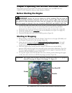
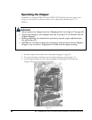
Before Starting the Engine
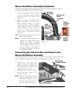
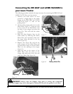
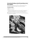
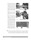
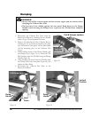
1. Connect the DR LEAF and LAWN VACUUM to your lawn tractor (see page 18) and
raise the three Support Legs into the mounting frame by repositioning the quick
release pins into the lower holes provided in the leg shafts (see Figure 18 on page 18).
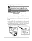
2. Check the engine oil level every time
you use the machine (see Figure 25 on page 23).
3. Check the gasoline level (see Figure 25).
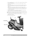
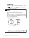
4. Turn the Gas Shut-Off valve to the OPEN position (Figure 26).
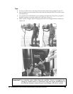
Starting & Stopping
1. When starting a cold engine; push the Choke Control lever to the right (CHOKE) and
the Throttle Control lever to the far right (Figure 26).
2. Grasp the recoil starter handle and slowly pull until you feel resistance, then pull
the cord with a smooth accelerating motion to start the engine. One or two pulls
usually starts the DR LEAF and LAWN VACUUM.
3. After the engine starts, slowly push the Choke Control lever to the left (RUN)
position. Wait until the engine runs smoothly before each choke adjustment (Figure 26).
For best engine performance, it is recommended that the engine be operated with the
throttle in the fast (Rabbit) position (Figure 26).
4. To stop the engine, move the throttle to the slow (Turtle) position allowing the engine
to idle, then move the lever to STOP (Stop Sign) position (Figure 26).
Figure 2
6
Choke
Gas Shut Off
Throttle
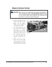
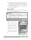
WARNING! Inspect the area in which you will be working. The site must be
free of potentially hazardous obstacles such as stones, metal or glass. Pile sticks that
y
ou intend to chip separately and away from the vacuum site. Also make sure there
w
on't be
p
eo
p
le or animals in the area around the DR LEAF and LAWN VACUUM.
Important! The engine will not start if the Safety Interlock Switches are not properl
y
adjusted. See page 16,
Figure 14
and page 37,
Figure 43.