


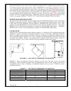
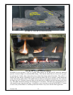
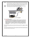
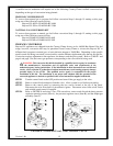
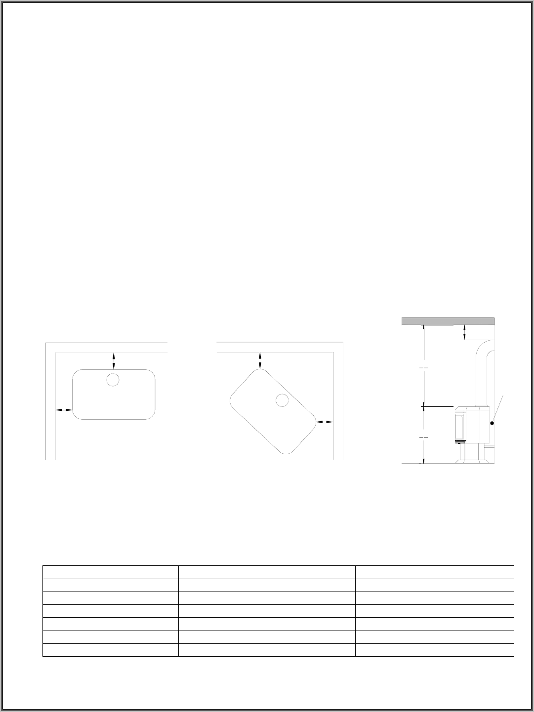
The SIT 820 NOVA mV gas control value, installed in the Bayvue DV, is supplied with pressure test ports
for checking input and output fuel pressures. Refer to FIGURE 27 for valve test port locations. Valve test
ports are located below the off/pilot/on control knob. The right port is the OUT (Manifold Pressure) test
port and the left port is the IN test port. Pressure is checked by turning the capture screw counterclockwise
2 or 3 turns and then placing tubing from the manometer over the test point. WARNING: After taking
pressure readings, turn the capture screw clockwise to reseal. Do not over torque. The installer should
provide a 1/8" N.P.T. plugged tapped hole** immediately upstream of the gas supply line connection to be
used for a test gauge connection. **NOTE: N.P.T. means American Standard Taper Pipe Thread
MINIMUM/MAXIMUM Btu RATES
The Bayvue DV’s SIT 820 NOVA mV gas control valve has a HI/LOW knob that is used to regulate the
appliance’s manifold gas pressure. Refer to FIGURE 27 for location of this manifold control valve. When
a pilot flame has been established and the appliance’s OFF/PILOT/ON control knob is in the “ON”
position, the manifold HI/LOW control knob can be used to adjust the appliances Btu rates. Turning the
HI/LOW valve to “HI” allows the appliance to operate at its maximum Btu output rating. Turning the
HI/LOW valve to “LOW” allows the appliance to operate at its minimum Btu output rating.
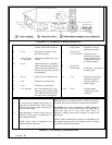
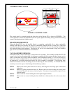
CLEARANCES
The Bayvue DV will heat nearby surfaces when in operation. A safe Bayvue DV installation requires that
minimum or greater clearances be maintained between the stove and nearby combustible materials.
Failure to maintain proper minimum clearances will cause overheating of combustible materials that can
lead to personal property damage or loss of life. Clearances around the appliance must allow for proper
servicing of the product. If there is any question about clearances please contact Country Flame or a
certified professional. Never reduce clearances below the minimums stated in this manual.
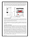
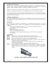
6"
6"
1"
1"
36"
30"
1"
6"
FIGURE 2: BAYVUE DV MINIMUM CLEARANCES
FIGURE 2 shows the minimum clearances required for back wall, side wall, corner, and ceiling
installations. These minimum clearances must be maintained in order to ensure proper service can be
accomplished and to ensure overheating of combustible materials does not occur. TABLE 2 lists the
minimum clearances.
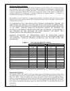
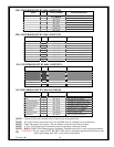
TABLE 2: BAYVUE DV MINIMUM CLEARANCES
Version 1.0h
7
CLEARANCE FROM DISTANCE (INCHES) DISTANCE (MILIMETERS)
LEFT/RIGHT SIDE WALL 6 152
FLOOR TO CEILING 66 1676
BACK WALL 6 152
UNIT TOP TO CEILING 36 914
HORIZONTAL FLUE 1 25
APPLIANCE CORNER 1 25