


PYROMASTER@ UVHB26 Vent-Free Heaters
A
WHEN INSTALLED, THE HEATER
MUST BEELECTRICALLY CON-
NECTED AND GROUNDED IN AC-
CORDANCE WITH LOCAL CODES
OR, IN THE ABSENCE OF LOCAL CODES:
U.S. INSTALLATIONS: FOLLOW LOCAL
CODES AND THE NATIONAL ELECTRICAL
CODE, ANSI/NFPA NO. 70.
D OPTIONAL
6. REMOTE WALL SWITCH (RN AND RP
MODELS ONLY)
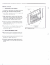
1. Thread wire through the square hole located
on either side of unit. Do not cut wire or insula-
tion on metal edges. Ensure that wire is pro-
tected. Run the other end to a conveniently
located wall receptacle box.
2. Attach wire to switch and install switch into
receptacle box. Attach cover plate to switch.
"'J
',>,.J'/
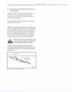
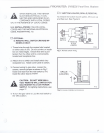
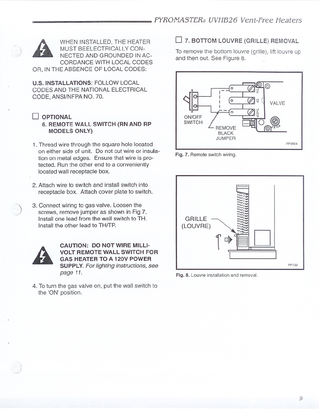
3. Connect wiring to gas valve. Loosen the
screws, remove jumper as shown in Fig 7.
Install one lead from the wall switch to TH.
Install the other lead to TH/TP.
A
CAUTION: DO NOT WIRE MILLI-
VOLT REMOTE WALL SWITCH FOR
GAS HEATER TO A 120V POWER
SUPPLY. For lighting instructions, see
page 11.
4. To turn the gas valve on, put the wall switch to
the 'ON' position.
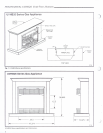
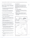
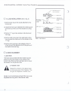
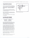
D 7. BOTTOM LOUVRE (GRILLE) REMOVAL
To remove the bottom louvre (grille), lift louvre up
and then out. See Figure 8.
VALVE
ON/OFF
SWITCH
FP382A
Fig. 7. Remote switch wiring.
=
"""'~
""', .~
""" ..
""" '0'
""""
"""'~
""'. .~
""""
"'01._..
""'1_'
"""'"
RILLE
~
.."'.,,~
G """'"
""".",
(LOUVRE) T.,.:; D
FP733
Fig. 8. Louvre installation and removal.
9