


PYROMASTER@ UVHB26 Vent-Free Heaters
0 4. OPTIONAL FK24 FAN HOOK-UP
NOTE: The FK24 fan should be installed before
the mantel cabinet is complete. Later installation
will be more difficult.
1. Remove the two (2) screws holding the screen
rods inside the bay top. Remove the screen
and rods then set aside.
2. Remove the bay top by removing three (3)
screws securing it to the combustion dome.
3. Tip out and lift the bay top and set aside.
4. Remove three (3) nuts securing the fan bracket
to the back of the heater.
5. Remove the (2) screws holding the bracket to
the fan. Discard this bracket.
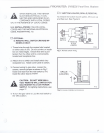
6. Remove the two (2) wires attached to the fan
and assemble the fan to the bracket as shown
in figure 6.
7. Attach the fan assembly to the back of the
heater with the three (3) nuts.
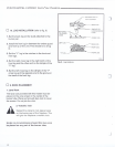
8. Attach the electrical flag connectors to the fan
motor using the wire extension (See fig. 5.)
9. Feed the wire down the 1-inch diameter hole in
the left side of the radiant shield. Push plastic
bushing in hole.
10. Hook the wire extension to the wire leads
from the fan control box. NOTE: These leads
were hooked to the motor earlier.
11. Mount the thermo-disc to the shield under the
burner pan and secure with two (2) nuts.
12. Mount the fan on-off control to the base with
the studs provided and secure with two (2)
nuts.
13. Feed the plug through the 4" x 5" hole on the
left side of the heater and plug into a wall
receptacle.
14. Repeat steps 1 through 3 to reassemble the
heater.
8
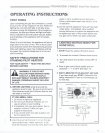
FAN OPERATION
The FK24 fan has a heat sensor that will not
allow the fan to come on until heater reaches a
preset temperature, approximately 100-120°F.
Once the heater reaches temperature use the
speed control knob to turn fan on and off to adjust
fan speed.
)
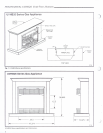
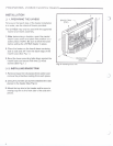
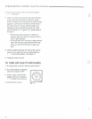
0 5. FINAL ASSEMBLY
1. Final assembly is accomplished by lifting the
mantel cabinet overtop of the heater behind the
brass trim pieces.
2. NOTE: The mantel is designed to fit flush to
the wall as a freestanding unit. If desired, it
may be secured to the wall with nails or screws
(not provided).
~
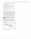
AN
TEMPERATURE
SENSOR,
SPEED ~
CONTROL~ .
~ r;. Wire
Extension
.)
FP394A
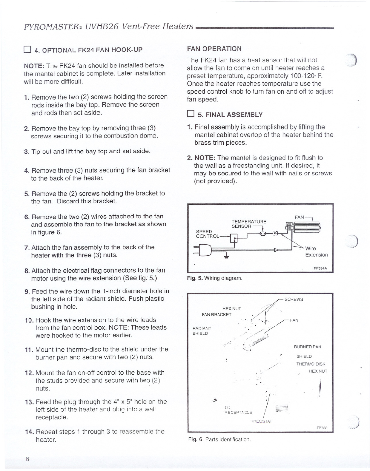
Fig. 5. Wiring diagram.
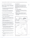
/
- SCREWS
HEXNUT --
FANBRACKET o! ',.
0' 0 (""'
V
l,: . FAN
RADIANT "", . ': '
SHIELD .. /.
/ ,0 '//~
,
/,"
,... -4
. .-/
':.;:;
BURNER PAN
//.
. ...-
, /
SHIELD
THERMO DISK
HEX NUT
I
-:-
/
'.
I ~~~~,
)
~",.I
TO
RECEPT,o,C:"'O
'1nEOSTAT
FP732
Fig. 6. Parts identification,