7
UV36RN/RP Vent-Free Gas Fireplaces
20007436
Installation & Operating Instructions
Locating the Fireplace
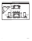
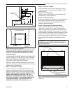
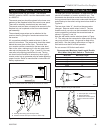
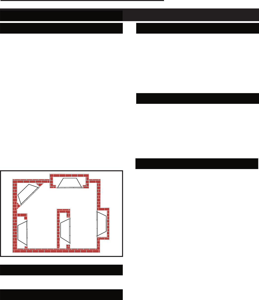
Figure 3 shows some of the many ways your fireplace
may be installed. Consider the traffic pattern in your
room and the location of doors and windows. Moving
air from ceiling fans, open doors and hot air grilles may
cause the flames to soot. If a disturbance is found that
affects the flames, it must be eliminated by turning off
the ceiling fan, closing the door or closing/moving the
hot air register. A corner location may be best where
space is limited.
Your fireplace weighs no more than some of your fine
furniture. If the fireplace is located near a load bearing
wall, additional supports to the foundation will not be
necessary.
NOTE: Heavy facings such as brick, stone, etc., may
require additional foundation support.
NOTE: Although this unit may be installed on com-
bustible surfaces, it must not be installed on carpet
or vinyl.
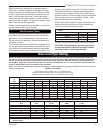
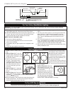
The clearances to sidewalls and ceiling that are shown
in Figures 5, 6a, 6b and 7 must be considered when
choosing the location for the fireplace.
LU584-1
Locating unit
2/4/99 djt
Partial Room
Projection
Corner
Full Room
Projection
Room
Divider
Flush
LU584-1
Fig. 3 Locating the fireplace.
Gas Line
The gas line must be installed by a licensed gas line
installer before framing in the fireplace.
Drafts
Do not locate the fireplace in high traffic areas or areas
exposed to high drafts and winds. Locate the fireplace
away from furniture and draperies.
Fan Kit - Optional
If the construction of your fireplace is with a full outer
casing and full bottom pan, use Blower Kit BL-4 or
FK12.
If the construction of your fireplace is with two sheet
metal legs supporting the combustion chamber at the
back, use Blower Kit BL-3. The variable speed control,
SCVS, is included with the BL-3.
Optional variable speed control, Model SCVS, may be
used with the Blower Kit BL-4.
Electrical Services
All optional fan kits are equipped with a 120V, 60Hz
blower, less than 12 amps.
A 120V outlet, Part no. EB-1, is needed in the fireplace
in order to plug in the optional blower accessory. The
blower is equipped with a standard 3-prong electrical
plug.
Installation Tip: The blower will be easier to install if
done at time of appliance installation.
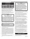
Framing Clearances
The fireplace may be placed directly on a combustible
floor, against a combustible wall at marked clearances
or on a raised wooden platform.
If the fireplace is to be installed on a raised wooden
platform, the platform must be a continuous level sur-
face.
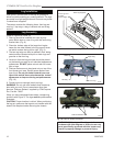
The fireplace must be secured in place so it cannot shift
positions. The nailing flanges on the sides of the fire
-
box make securing it to the framing easy. They were
designed to allow the installation of 1/2” wallboard or
plywood flush with the face of the fireplace.
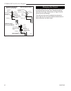
Only the header (Fig. 4) may rest on the standoffs on
top of the firebox. Framing must rest on top of stand-
offs.
When the fireplace is installed over carpeting, vinyl tile
or any combustible material other than wood flooring,
it must be installed on a metal or wood panel extend-
ing its full width and depth. Alternatively - the carpet-
ing, vinyl tile, etc., may be removed from beneath the
fireplace before installing.
Combustible materials must not be installed over or
touch the black front surface of the fireplace.


