15
UV36RN/RP Vent-Free Gas Fireplaces
20007436
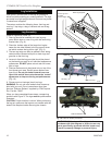
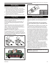
If the pilot cannot be ignited with the piezo, it can be manually
lit with the use of a match and lighter rod.
1. Place the match in the holder and light. With the right
hand, depress and turn the control knob counterclockwise
to the PILOT position. Hold in for 20 seconds.
2. Take the lighter rod and lighted match and ignite the pilot.
3. Continue to hold the control knob for an additional 20
seconds to ensure pilot is maintained.
4. Proceed with Step 8 in the Lighting Instructions on Page
14.
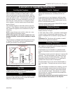
Match Lighting
Flame Check
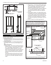
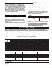
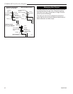
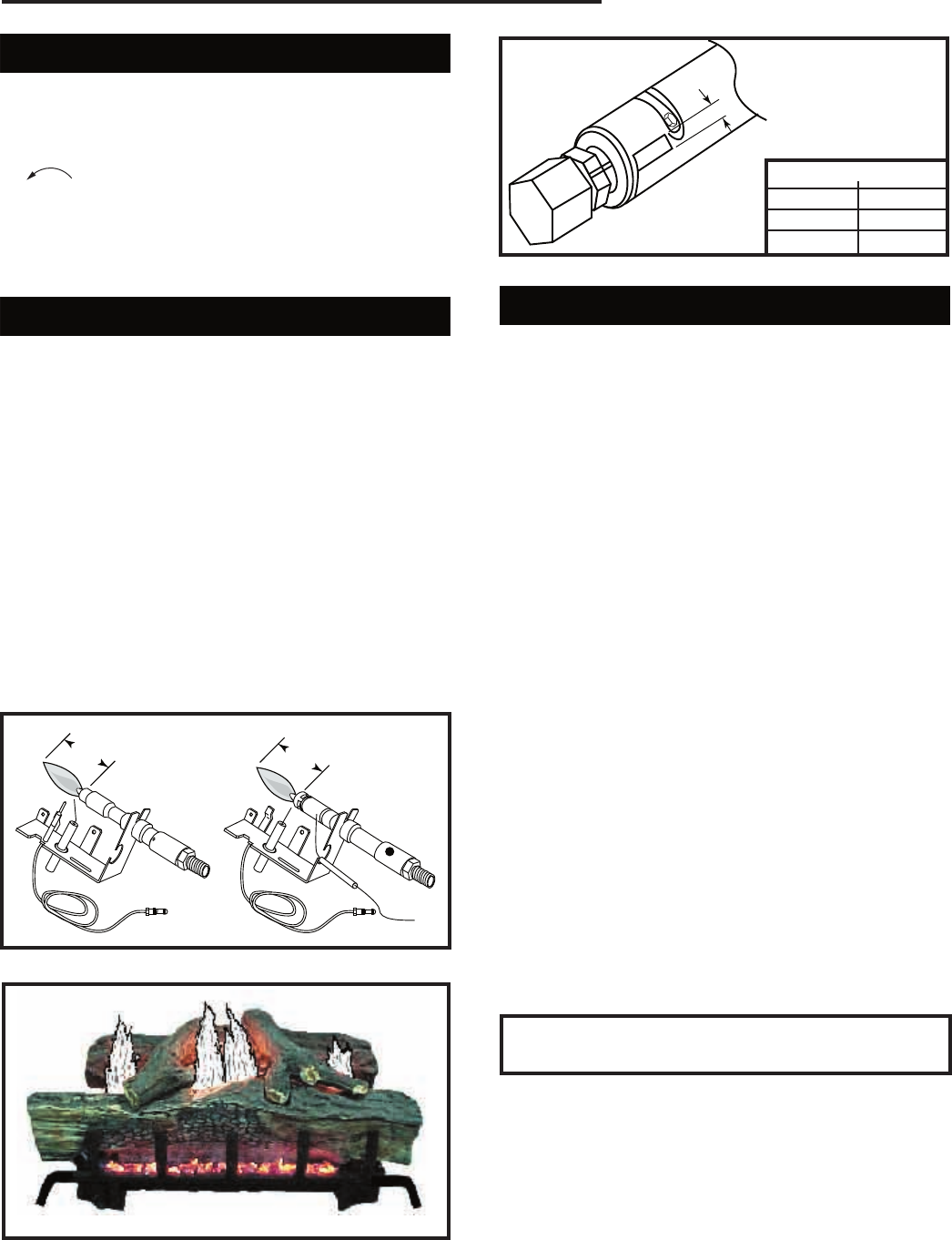
A periodic visual check of the flames should be made.
The pilot flame should always be present when the ap-
pliance is in operation. (Fig. 21)
In normal operation (at full rate for approximately 15
minutes) the following flame appearance should be
observed:
The flame should burn blue with some yellow flames
visible. Height of the blue flame should be approxi
-
mately 1” on high. The yellow flames should extend 6
to 8 inches above the large front log.
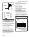
Typical flame shape seen in Figure 22.
NOTE: For your safety, the appliance is equipped with
an oxygen depletion system. The system senses the
oxygen in the atmosphere and switches off the gas sup-
ply in case the level of oxygen falls below a safe level. It
must not be altered in any way.
T140
Temco manual
pilot flame
10/27/03 djt
1¹⁄₂"
1¹⁄₂"
T140
Natural Gas
Propane
Fig. 21 Pilot flame position and location.
TL108
Fig. 22 Correct burner flame appearance.
A
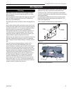
Air Shutter Settings
Model A
UV36RN 0.125”
UV36RP 0.375”
T134
Fig. 23 Air shutter settings.
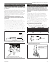
Finishing the Fireplace
There are a wide variety of finishing materials avail-
able for your fireplace, from formal wall treatments with
marble and mantels to rustic wood paneling, stone or
brick.
It is important that the black face of the fireplace
not be covered with any type of combustible mate-
rial.
Noncombustible facing materials such as marble, brick
or ceramic tile may overlap the black face of the fire-
place up to the opening on either side of the fireplace.
Seal all joints between the black fireplace face and the
wall covering with a heat resistant material such as rock
wool insulation or mortar. Be sure to use high tempera-
ture adhesive or mortar when anchoring brick, stone or
tile to the face of the fireplace. Check to see whether
man-made brick and stone are made of noncombustible
materials before using them on the face of the fireplace.
Some of these products contain combustible materials.
Combustible wall coverings such a paneling or wall-
board may not overlap the black face of the fireplace.
The space between the wall covering and the fireplace
should be sealed with a heat resistant material such as
rock wool insulation or mortar.
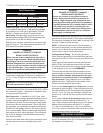
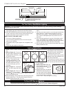
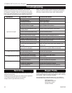
NOTE: An “L” shaped steel lintel must be installed
across the top of the firebox opening where facing
materials such as brick or stone are used on the face
of the firebox. It acts as a support/firestop. It should be
attached to the face of the fireplace with screws and
sealed to the fireplace with a heat resistant sealer. Re-
fer to Figure 24 for finishing options.
WARNING: These vent free fireplaces are not to
be used with glass doors.


