


9
W415-0298 / K / 12.06.07
A
C
B
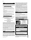
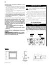
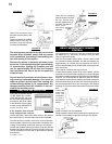
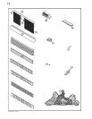
FIGURE14
HOOD
Attach the hood by pressing the
top fl ange into the clips along
the top of the louvre opening.
Secure using a screw through
the centre slot.
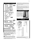
A
CLIPS
CENTRE
SLOT
FLANGE
UPPER LOUVRES
Insert the louvre tabs into the
slots located at the top left and
right corners of the unit.
SLOT
TAB
B
LOWER LOUVRES
Insert the hinge clips into the
slots located at the bottom left
and right corners of the unit.
To remove the louvres, pull the
back tabs of the clips forward,
while pushing the louvre assem-
bly back. Lift the clip.
C
HINGE
CLIP
SLOT
L36 LOUVRE INSTALLATION
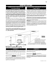
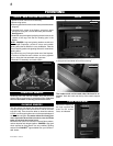
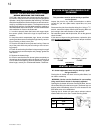
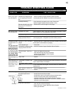
OPTIONAL BLOWER INSTALLATION
C
A
B
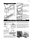
FIGURE 17
FIGURE 15
FIGURE 16
INSTALLATION TO BE DONE BY A QUALIFIED INSTALLER
and must be electrically connected and grounded in accord-
ance with local codes. In the absence of local codes, use the
current ANSI/NFPA 70 NATIONAL ELECTRICAL CODE.
If the fireplace was not
previously equipped
with a blower: route a
grounded 2-wire, 60hz
power cable to the junc-
tion box. At this point, it
must be strain relieved
and insulated.
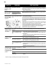
The three slots on the
blower mounting bracket
allow ease of adjustment
when attaching the blow-
er. For a quiet running
blower, do not allow the
assembly to sit on the
fi rebox base.
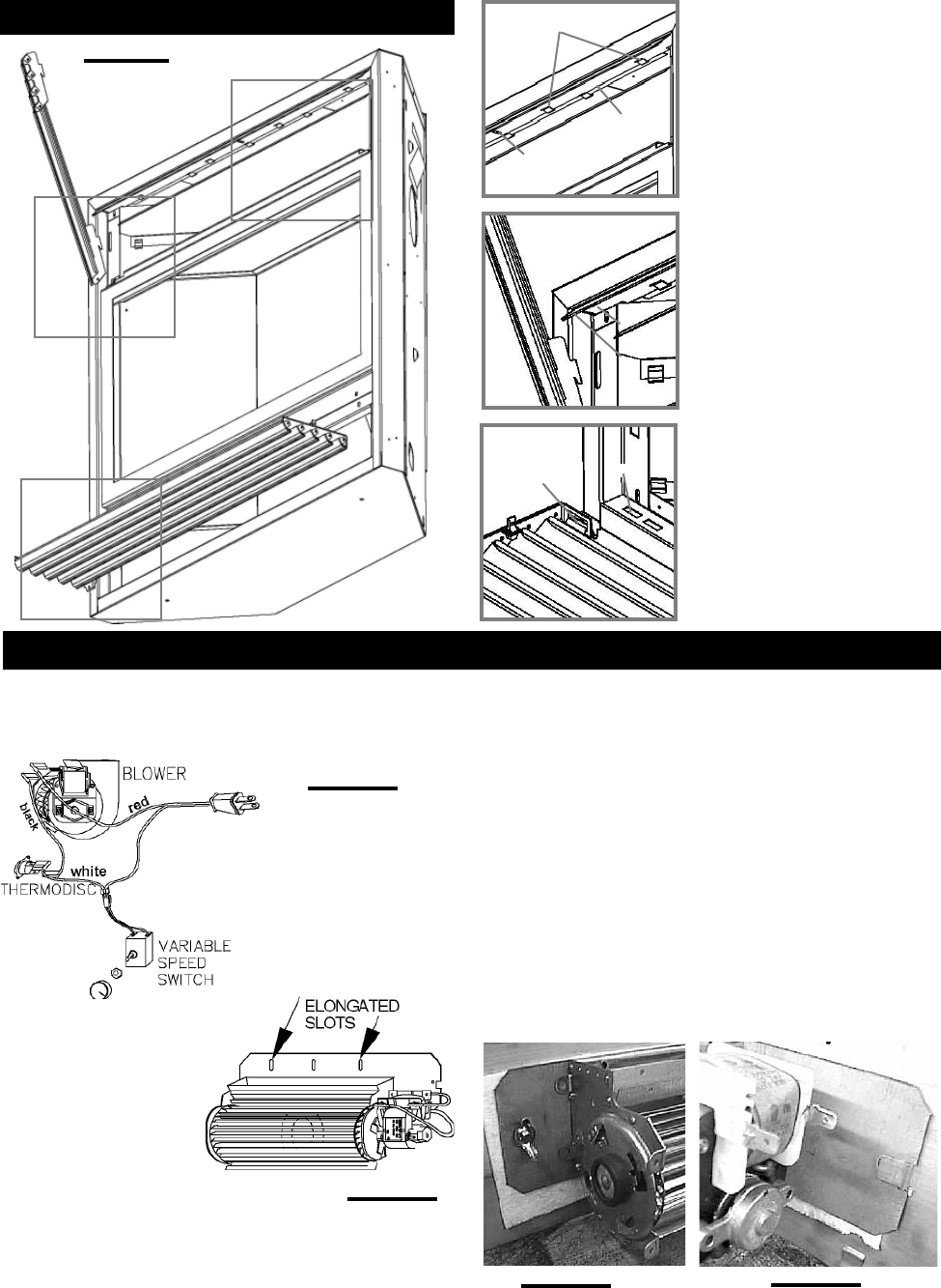
the bracket before installing the blower. Attach the black and
white wires to the disc, then secure the bracket to the stud
at the bottom left on the unit using the lock washer and wing
nut. Ensure that the thermodisc touches the fi rebox wall.
Slide the vibration reducing pad (A) into the clip (C) and up
against the threaded stud (B) at the other end. The blower
must be able to be positioned entirely onto the pad.
Tilt the blower onto its side. Slide it past the controls and
into the clip (C). Secure to the threaded stud using the lock
washer and wing nut provided. Ensure that the blower does
not touch the fi replace base or the fi rebox.
If optional blower kit is to be installed, remove thermodisc
from the bracket supplied in the kit and disgard the bracket.
Install thermodisc in the bracket supplied with the fi replace. It
is recommended to attach the wires to the disc and install
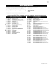
FIGURE 18