


6
W415-0298 / K / 12.06.07
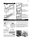
Proceed once the vent installation is complete.
NOTE: All gas connections must be contained within
the fi replace when complete.
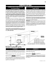
1. Move the fi replace into position and secure to the fl oor
through the 1/4" holes located at either side of the base.
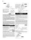
2. The fi replace is designed to accept 3/8" gas supply line.
The fi replace is equipped with a 3/8" manual shut-off valve.
3. Connect the gas supply in accordance to local codes.
In the absence thereof, install according to the National
Installation Code.
4. When fl exing any gas line, support the gas valve so
that the lines are not bent or kinked.
5. Check for gas leaks by brushing on a soap and water
solution.
DO NOT USE OPEN FLAME.
Unusually tight construction is defined as con-
struction where:
a) Walls and ceilings exposed to the outside atmosphere
have a continuous water vapour retarder with a rating of
1 perm (6 x 10
-11
kg per pa-sec-m
2
) or less with openings
gasketed or sealed, and
b) Weather stripping has been added on openable win-
dows and doors, and
c) Caulking or sealants are applied to areas such as
joints around window and door frames, between sole plates
and fl oors, between wall-ceiling joints, between wall panels,
at penetrations for plumbing, electrical, and gas lines, and
at other openings.
An unvented room heater is recommended for use as a
secondary heat source rather than as a primary source.
Gas combustion produces water vapour which could occur
at the rate of approximately one ounce of water for every
1,000 BTU/hr of gas input. During the cold weather season,
indoor humidity levels tend to be low. Consequently, this
water vapour can enhance the living space. However if a
problem should occur:
a) ensure suffi cient combustion and circulation air
b) use a dehumidifi er
c) do not use the unvented room heater as a primary
heat source
Without suffi cient fresh air for proper operation, poor fuel
combustion can result. Carbon Monoxide is a result of poor
combustion.
If additional fresh air is required, use one of the meth-
ods described in the National Fuel Gas Code, ANSI Z223.1,
Section 5.3 or the applicable local code.
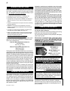
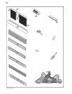
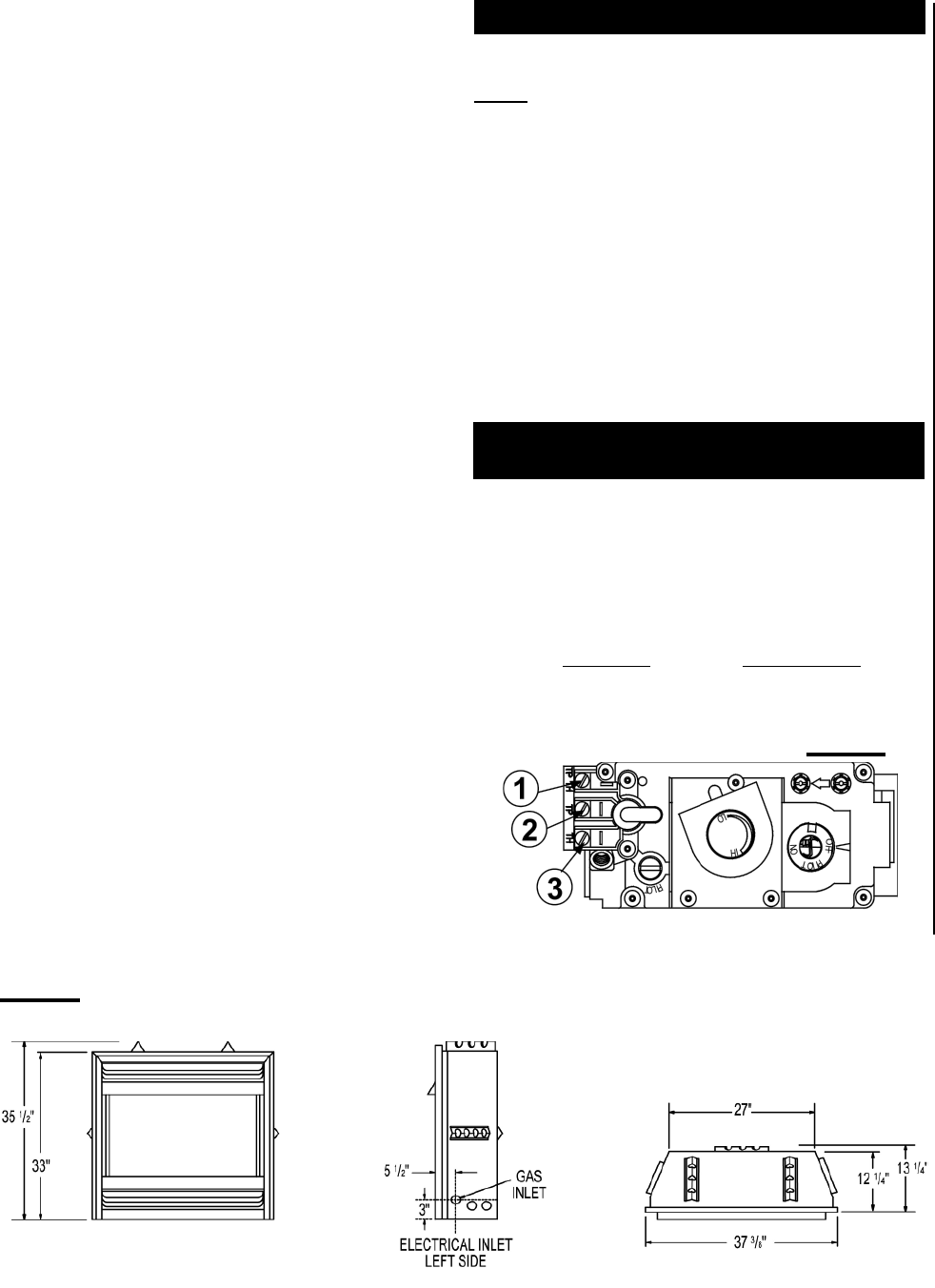
GAS INSTALLATION
FIGURE 3
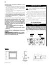
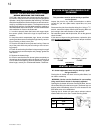
For ease of accessibility, an optional remote wall switch may
be installed in a convenient location. A 20’ length of millivolt
wire is connected to the gas valve for the wall switch. How-
ever if a greater length is required route 2-strand (solid core)
millivolt wire through the electrical hole located at the bottom
left side of the unit. The recommended maximum lead length
depends on wire size:
WIRE SIZE MAX. LENGTH
14 gauge 100 feet
16 gauge 60 feet
18 gauge 40 feet
OPTIONAL WALL SWITCH
INSTALLATION
FIGURE 2