


10
W415-0298 / K / 12.06.07
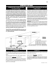
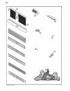
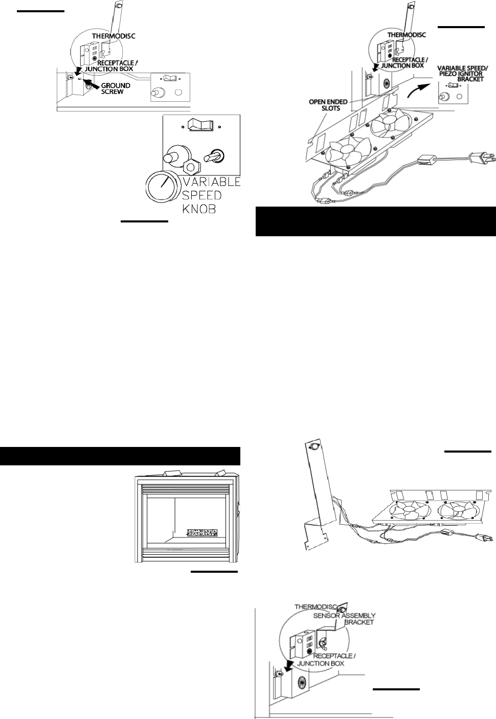
FIGURE 22
FIGURE 20
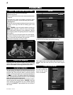
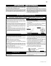
Attach the connectors from
the black and red wires to the
blower.
Attach and secure the variable
speed switch using the nut
provided. Plug the harness
cord into the receptacle.
The wire harness provided in this kit is a universal
harness. When installed, ensure that any excess
wire is contained, preventing it from making con-
tact with moving or hot objects.
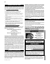
Because the blower is thermally activated, when
turned on, it will automatically start approximately
10 minutes after lighting the fireplace and will
run for approximately 30-45 after the fireplace
has been turned off. Use of the fan increases the
output of heat.
Drywall dust will penetrate into the blower bear-
ings causing irreparable damage. Care must be
taken to prevent drywall dust from coming into
contact with the blower or its compartment. Any
damage resulting from this condition is not cov-
ered by the warranty policy.
FIGURE 19
This optional kit is meant to be used only in conjunction with
the GD65 Fan Kit, which may be ordered from your Wolf
Steel /Continental® dealer.
With the thermostatic sensor option, the fan, when turned
on, becomes thermally activated, and will automatically run
approximately 10 minutes after the fi replace has been lit
and for approximately 30-45 minutes after the fi replace has
been turned off.
Use of the fan increases the output of heat.
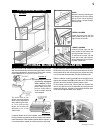
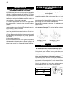
If optional thermostatic sensor kit is to be installed, remove
thermodisc from the bracket supplied in the kit and disgard
the bracket. Install thermodisc in the bracket supplied with the
fi replace. It is recommended to attach the wires to the disc
and install the bracket before installing the blower. Attach the
black and white wires to the disc, then secure the bracket to
the stud at the bottom left on the unit using the lock washer
and wing nut. Ensure that the thermodisc touches the fi rebox
wall.
Unplug the
power cord
from the
receptacle.
Connect
all wires as
shown.
Plug the
power cord back into the receptacle.
When installed, ensure that any excess wire is contained, pre-
venting it from making contact with moving or hot objects.
FIGURE 24
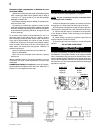
ELECTRICAL INSTALLATION
TO BE DONE BY A QUALI-
FIED INSTALLER and must
be connected and grounded in
accordance with local codes.
In the absence of local codes,
use the current ANSI/NFPA 70
NATIONAL ELECTRICAL CODE.
If the fireplace was not previ-
ously equipped with a blower,
route a grounded 2-wire, 60hz power cable to the junction
box. At this point, it must be strain relieved and insulated.
The wire harness provided in this kit is a universal harness.
When installed, ensure that any excess wire is contained, pre-
venting it from making contact with moving or hot objects.
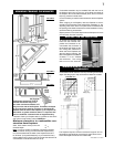
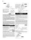
Position the vibration reducing pad into the clip and onto the
threaded stud at the other end, piercing a hole into the pad.
The fan assembly must be able to be positioned entirely
onto the pad.
FIGURE 21
FIGURE 23
GD65 FAN INSTALLATION
GD36 THERMOSTATIC SENSOR
CONTROL
Slide the fan assembly
past the controls and into
the clip. Secure using
the lock washer and nut
provided. Plug the har-
ness cord
into the re-
ceptacle.