


111044-01D
For more information, visit www.desatech.com
For more information, visit www.desatech.com
14
CONNECTING TO GAS SUPPLY
WARNING: A qualified service person must con-
nect fireplace to gas supply. Follow all local codes.
CAUTION: Never connect propane/LP fireplace
directly to the propane/LP supply. This fireplace
requires an external regulator (not supplied). Install
the external regulator between the fireplace and pro-
pane/LP supply.
CAUTION: Use only new, black iron or steel
pipe. Internally-tinned copper tubing may be used
in certain areas. Check your local codes. Use pipe
of 1/2" or greater diameter to allow proper gas
volume to fireplace. If pipe is too small, undue loss
of volume will occur.
WARNING: Use pipe joint sealant that is resistant
to liquid petroleum (LP) gas.
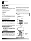
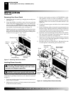
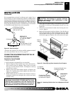
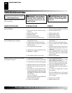
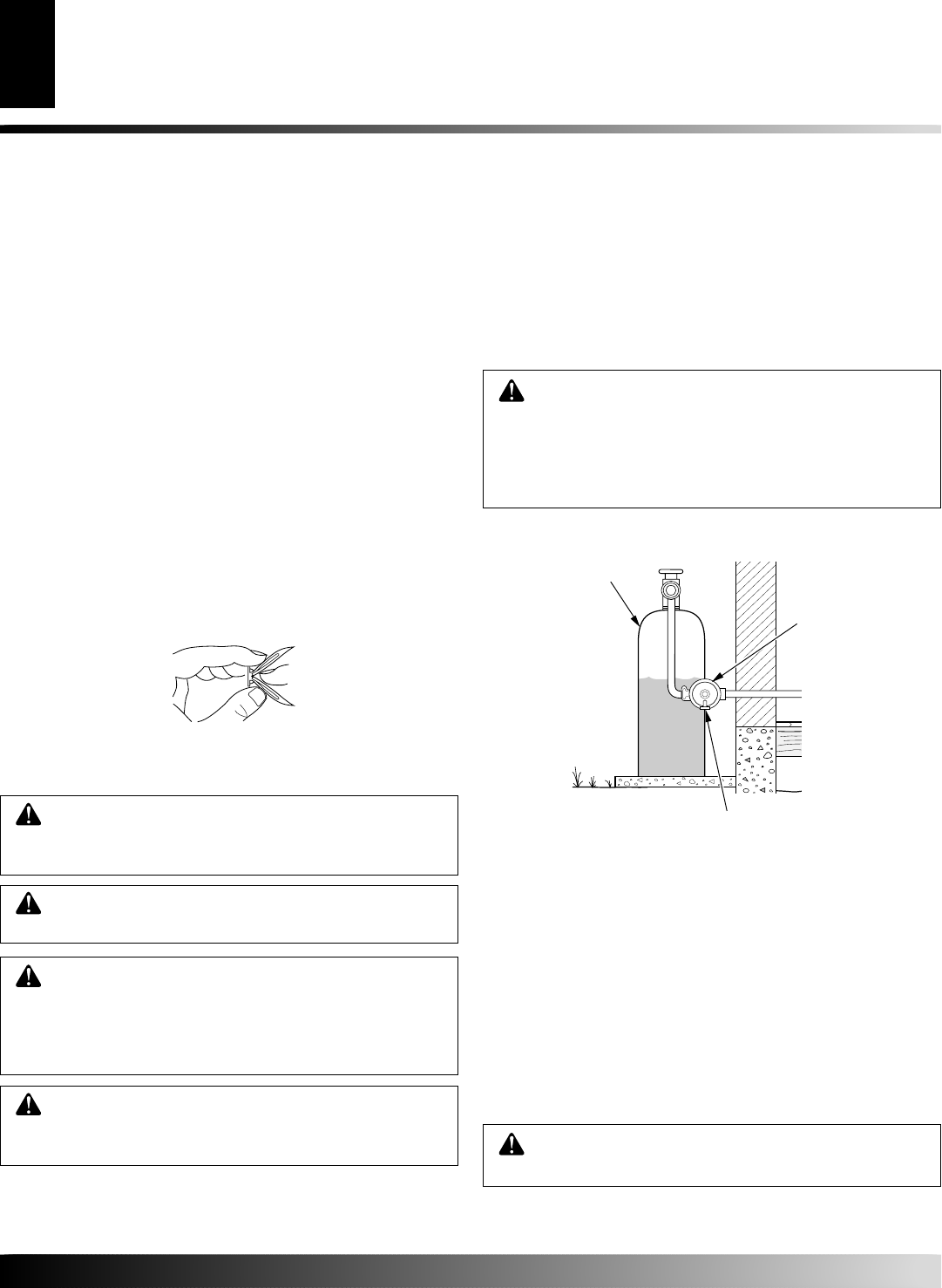
For propane/LP units, installer must supply an external regulator.
The external regulator will reduce incoming gas pressure. You must
reduce incoming gas pressure to between 11 and 14 inches of water.
If you do not reduce incoming gas pressure, fireplace regulator
damage could occur. Install external regulator with the vent point-
ing down as shown in Figure 23. Pointing the vent down protects it
from freezing rain or sleet.
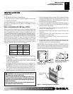
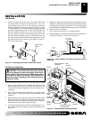
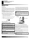
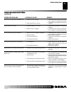
Installation must include an equipment shutoff valve, union, and
plugged 1/8" NPT tap. Locate NPT tap within reach for test gauge
hook up. NPT tap must be upstream from fireplace (see Figure 24).
IMPORTANT:
Install an equipment shutoff valve in an accessible
location. The equipment shutoff valve is for turning on and shutting
off the gas to the appliance.
Check your building codes for any special requirements for locating
equipment shutoff valve to fireplaces.
Apply pipe joint sealant lightly to male NPT threads. This will
prevent excess sealant from going into pipe. Excess sealant in pipe
could result in clogged fireplace valves.
Propane/LP
Supply Tank
Vent Pointing Down
External Regulator
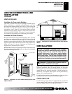
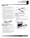
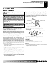
ATTACHING WOOD BASE TO SOLID FLOOR
For attaching base to solid floors (concrete or masonry)
Note:
Floor anchors and mounting screws are in hardware package.
The hardware package is provided with fireplace.
1. Drill holes at marked locations using 5/16" drill bit. For solid
floors (concrete or masonry), drill at least 1" deep.
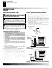
2. Fold floor anchor as shown in Figure 22.
3. Insert floor anchor (wings first) into hole. Tap anchor flush
to floor.
4. Insert mounting screws through base and into floor anchors.
5. Tighten screws until base is firmly fastened to floor.
Figure 22 - Folding Anchor
Figure 23 - External Regulator with Vent Pointing Down
INSTALLATION
Continued
WARNING: This appliance requires a 45° male flare
fitting 5/8"-18 UNF (Unified National Fine Thread) inlet
connection and the flexible gas line provided.
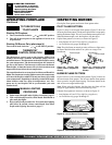
Extension Cord
Use extension cord if needed. The cord must have a three-prong,
grounding plug and a three-hole receptacle. Make sure cord is in good
shape. It must be heavy enough to carry the current needed. An
undersized cord will cause a drop in line voltage. This will result in
loss of power and overheating. Use a No. 16 AWG cord for lengths
less than 50 feet.
WARNING: Never connect natural gas fireplace to
private (non-utility) gas wells. This gas is commonly
known as wellhead gas.
INSTALLATION
Installing Blower Accessory - GA3450T (Cont.)
Attaching Wood Base to Solid Floor
Connecting to Gas Supply