


111044-01D
For more information, visit www.desatech.com
For more information, visit www.desatech.com
11
11
INSTALLATION
Continued
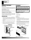
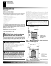
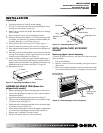
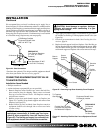
Figure 14 - Attaching Wood Base to Floor
1
3
/4" Screw
Wood Base
6. Align brass trim kit for flush fit around opening.
7. Use two 3" wood screws provided and attach fireplace base to
wooden base (see Figure 13, page 10).
8. Remove brass trim kit and mantel. Be careful not to damage
wall or mantel.
9. Place wood base next to wall at installation location.
10.
Attach wood base to floor with two 1
3
/
4
" black screws provided
(see Figure 14). If the floor is concrete use anchor method (see
Attaching Wood Base to Solid Floor, page 14).
11. Install gas line. See Connecting To Gas Supply, page 14.
12. Check for leaks. See Checking Gas Connections, page 16.
13. Place mantel around fireplace. Be careful not to damage wall
or mantel.
14. Place brass trim kit on the shoulder screws located on the side
and top of the fireplace. Firmly snap the brass trim over the
shoulder screws on fireplace (see Figure 13).
15. Adjust assembly to remove any gaps. Attach remaining two 3"
wood screws from hardware pack through openings inside of
fireplace sides into the mantel. The openings are located at top
behind the area for the louvers (see Figure 13, page 10).
16. Reinstall top louvers.
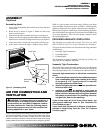
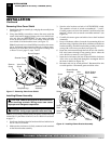
ASSEMBLING BRASS TRIM (Brass trim
shipped with mantel)
1. Remove packaging from three remaining pieces of brass trim.
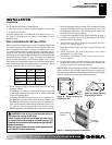
2. Locate two adjusting plates with set screws, and two shims in
the hardware packet.
3. Align shim under adjusting plate as shown in Figure 15.
4. Slide one end of adjusting plate/shim in slot on mitered edge
of top brass trim (see Figure 15).
5. Slide other end of adjusting plate/shim in slot on mitered edge
of side brass trim (see Figure 15).
6. While firmly holding edges of brass trim together, tighten both
set screws on the adjusting plate with slotted screwdriver.
7. Repeat steps 1 through 6 for other corner.
8. Set brass assembly aside for later installation.
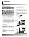
Figure 15 - Assembling Brass Trim
Side Brass Trim
Top Brass Trim
Mitered Edge
Shim
Set Screws
Adjusting
Plate
Slot
Slot
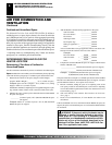
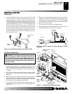
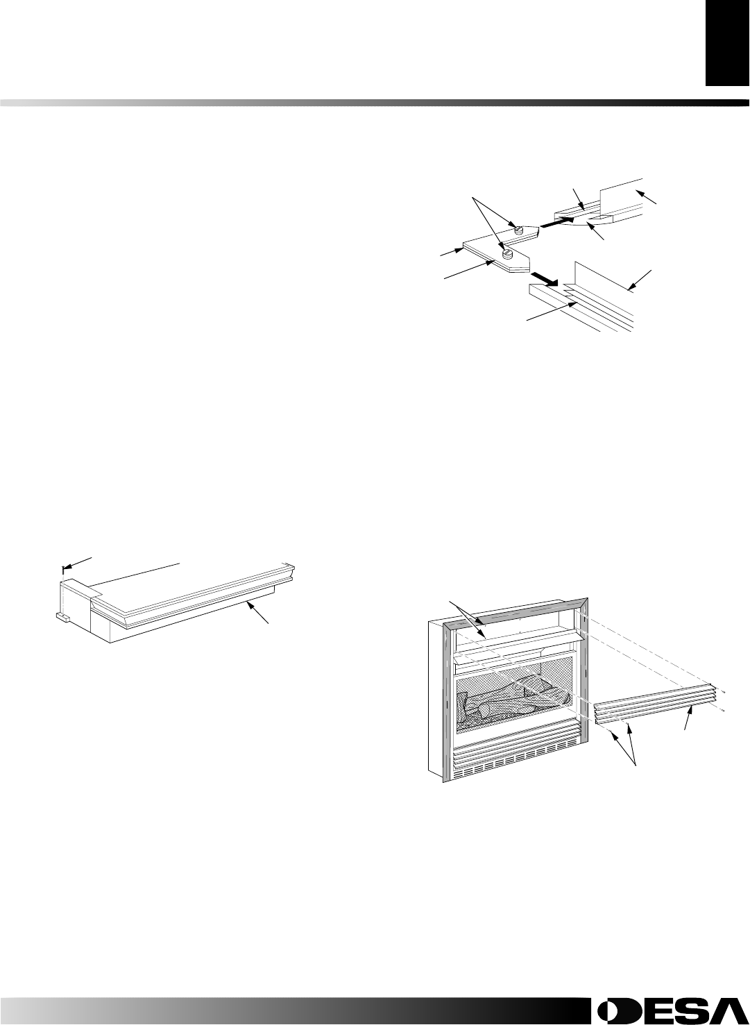
INSTALLING BLOWER ACCESSORY
GA3450T
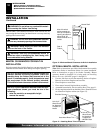
Removing Upper Louver Assembly
To install the blower accessory, you must first remove the upper
louver assembly.
1. Lift screen off heater.
2. Remove 4 screws from louver assembly (see Figure 16). Save
these screws.
3. Pull louver assembly straight out from the cabinet. Be careful
not to scratch the paint. Set louver assembly and screws aside.
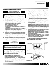
Figure 16 - Removing Upper Louver Assembly
Upper Louver
Assembly
Screws
Blower Bracket
Mounting Holes
INSTALLATIONS
Optional Mantel Installation (Cont.)
Assembling Brass Trim
Installing Blower Accessory - GA3450T