


111044-01D
For more information, visit www.desatech.com
For more information, visit www.desatech.com
10
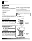
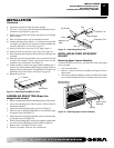
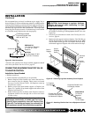
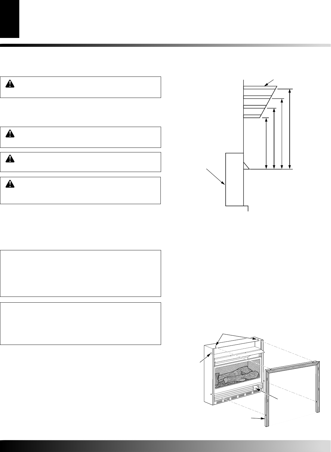
13"
16"
19"
21"
2
1
/2"
6"
8"
10"
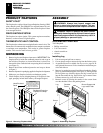
Note:
All vertical
measurements
are from top of
fireplace
opening to
bottom of
mantel shelf. All
measurements
are in inches.
MANTEL CLEARANCES FOR BUILT-IN
INSTALLATION
If placing mantel above built-in fireplace, you must meet minimum
clearance between mantel shelf and top of fireplace opening.
Figure 12 - Minimum Mantel Clearances for Built-In Installation
Mantel Shelf
Side of
Firebox
INSTALLATION
Continued
NOTICE: Surface temperatures of adjacent walls and
mantels become hot during operation. Walls and
mantels above the firebox may become hot to the
touch. If installed properly, these temperatures meet
the requirement of the national product standard.
Follow all minimum clearances shown in this manual.
NOTICE: If your installation does not meet the mini-
mum clearances shown, you must do one of the
following:
• raise the mantel to an acceptable height
• remove the mantel
WARNING: Do not allow any combustible materi-
als to overlap the firebox front facing.
IMPORTANT:
Noncombustible materials such as brick, tile, etc.
may overlap the front facing, but should never cover any necessary
openings like louvered slots.
WARNING: Do not allow noncombustible materials
to cover any necessary openings like louvered slots.
WARNING: Use only noncombustible mortar or
adhesives when overlapping the front facing with
noncombustible facing material.
WARNING: Never modify or cover the louvered
slots on the front of the firebox.
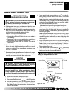
Note:
All vertical
measurements are
from top of fireplace
opening to bottom of
mantel shelf. All
measurements are in
inches.
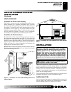
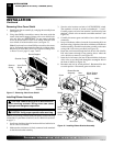
OPTIONAL MANTEL INSTALLATION
Note:
Refer to instructions provided with the mantel for assembly
instructions. Refer to instructions below for system installation.
Refer to instructions on page 4 for firebox assembly. Blower
accessory should be installed if it is being used (see Installing
Blower Accessory GA3450T, pages 11 through 13).
1. Unscrew four brass screws that attach top louver to fireplace.
Remove louver from fireplace and set aside.
2. Place fireplace on wood base.
3. Place mantel around fireplace/base assembly.
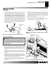
4. Assemble brass trim kit. See Assembling Brass Trim, page 11.
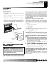
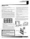
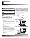
5. Firmly snap brass trim kit on shoulder screws. Shoulder screws
are located on fireplace cabinet (see Figure 13).
Shoulder Screws
Assembled Brass Trim
Hole for 3"
Wood Screw
for Attaching
Fireplace to
Wooden Base
Hole for 3"
Wood Screw
for Attaching
Fireplace to
Mantel
Figure 13 - Attaching Brass Trim to Fireplace
INSTALLATION
Built-In Fireplace Installation (Cont.)
Mantel Clearances for Built-In Installation
Optional Mantel Installation