


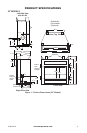
www.fmiproducts.com
124970-01A 13
INSTALLATION
Continued
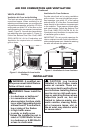
Model BK Installation
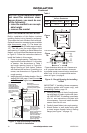
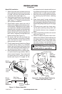
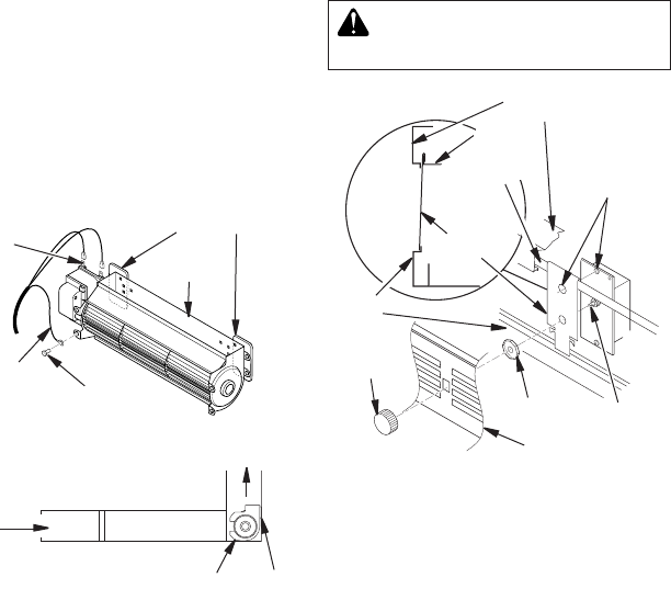
1. Attach the power cord to blower motor by
rmly pushing two female terminals at end
of power cord onto two spade terminals
on blower motor (see Figure 11).
2. Attach green ground wire from power cord
to blower housing using screw provided
(see Figure 11). Tighten screws securely
with a phillips screwdriver.
3. Place blower against lower rear wall of
rebox outer wrapper with exhaust port di-
rected upward. Depending on your model,
you may have to carefully route the blower
assembly past controls and brackets and
position blower inside back opening. The
blower will be held in position against the
back wall by magnets incorporated onto
blower housing (see Figure 11).
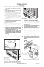
4. Be certain that all wire terminals are
securely attached to terminals on blower
motor and that the screw retaining the
green ground wire is tight.
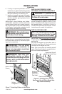
5. Position speed control bracket over ange
on hearth pan by sliding it up between
rebox face and hearth pan ange, then
down until seated onto lower ange of lou-
ver opening (see Figure 12, page 14).
6. Mount speed control box by placing plas-
tic control shaft through bottom hole on
speed control bracket. Top screw head
on control box will t inside top hole on
bracket (see Figure 12 on page 14). Se-
cure speed control to bracket with lock nut
by pushing and turning lock nut with pliers
clockwise until it is tight against bracket.
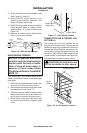
7. Remove knockout plug from louver panel
by pressing top and bottom retaining
clips.
8. Place louver panel, louvers pointing up,
back into framed opening. Align control shaft
with rectangular opening by sliding control
bracket along ange (see Figure 12 on page
14).
9. Fully seat louver panel into frame open-
ing by gently pressing along ends until
all dimpled retainers have snapped in
place.
10. Place control knob, provided, onto control
shaft (see Figure 12).
11. Check to make sure power cord is com-
pletely clear of blower wheel and there are
no foreign objects in blower wheel. Also,
double check all wire leads and make
sure wire routing is not pinched or in a
precarious position. Correct accordingly.
-
Figure 11 - Blower Model BK
Magnetic Strips
Exhaust
Port
Screw
Green
Ground
Wire
Spade
Terminals
Side View
Firebox Bottom
Air Flow
Direction
Blower
Installed
After
Lower
Panel
Removed
Blower
Location
Magnets
Figure 12 - Attaching Speed Control to
Firebox with Panel Louvers
Control
Shaft
Control
Knob
Lock Nut
Speed
Control
Bracket
Lower
Louver
Firebox Face
Hearth
Pan
Flange
Screw
Head and
Top Hole
on Bracket
Lower
Flange