


NOTICE
INSTALLATION STEP 2
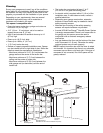
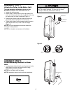
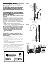
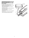
Attach the Emergency Release Rope
and Handle
• Thread one end of the rope through the hole in the top
of the red handle so “NOTICE” reads right side up as
shown. Secure with an overhand knot at least 1"
(2.5 cm) from the end of the rope to prevent slipping.
• Thread the other end of the rope through the loop in
the emergency release cable.
• Adjust rope length so the handle is no higher than 6'
(1.83 m) above the floor. Secure with an overhand
knot.
NOTE: If it is necessary to cut the rope, heat seal the cut
end with a match or lighter to prevent unraveling.
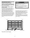
To prevent possible SERIOUS INJURY or DEATH from a
falling garage door:
• If possible, use emergency release handle to disengage
door ONLY when garage door is CLOSED. Weak or broken
springs or unbalanced door could result in an open door
falling rapidly and/or unexpectedly.
• NEVER use emergency release handle unless garage
doorway is clear of persons and obstructions.
Motor Unit
Emergency
Release Cable
Overhand
Knot
Rope
Emergency
Release Handle
Overhand
Knot
Figure 1
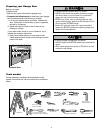
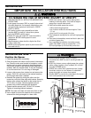
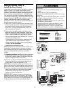
INSTALLATION STEP 3
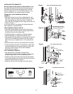
Install Power Door Lock
The lock is used to prevent the garage door from
being manually opened once the door is fully closed.
TOP
DRILL 5/16"
1. Select a door roller to mount the lock above. Check for
clearance. If possible select a roller on the same side
DRILL 3/4"
of the door as the motor unit. The second roller up
Approx. 3"
132A2505
DRILL 5/16"
from the bottom is ideal in most installations.
(7.6 cm)
Garage
2. Ensure rail surface is clean and adhere lock template
Door Track
with bottom edge just above the highest point on the
roller (Figure 1).
Lock Template
3. Drill holes as marked on the template.
TOP
DRILL 5/16"
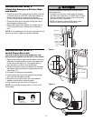
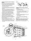
4. Fasten power door lock to the outside of the garage
DRILL 3/4"
door track with hardware provided.
132A2505
DRILL 5/16"
5. Run bell wire up wall to motor unit. Use insulated
Roller
staples to secure wire in several places.
6. Plug connector into the motor unit (Figure 2).
Figure 2
NOTE: Lock must be mounted within 10' (3 m) of the
power head.
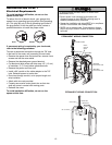
HARDWARE SHOWN ACTUAL SIZE
Lock Screw
Staples
1/4-20 x 1/2" (2)
8