


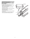
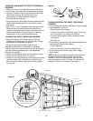
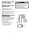

MOUNTING AND WIRING THE SAFETY REVERSING Figure 5
SENSORS
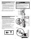
Wing Nut
1/4"-20
• Slide a 1/4"-20x1/2" carriage bolt head into the slot on
each sensor. Use wing nuts to fasten safety reversing
sensors to brackets, with lenses pointing toward each
other across the door. Be sure the lens is not
Carriage Bolt
obstructed by a bracket extension (Figure 5).
1/4"-20x1/2"
Lens
• Finger tighten the wing nuts.
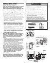
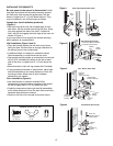
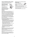
• Run the wires from both safety reversing sensors to the
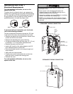
TROUBLESHOOTING THE SAFETY REVERSING
opener. Use insulated staples to secure wire to wall
SENSORS
and ceiling.
1. If the sending eye indicator light does not glow steadily
• Strip 7/16" (11 mm) of insulation from each set of wires.
after installation, check for:
Separate white and white/black wires sufficiently to
• Electric power to the opener.
connect to the opener quick-connect terminals: white to
white and white/black to grey (Figure 6). To insert or
• A short in the white or white/black wires. These can
release wires, push in tab with screwdriver tip.
occur at staples, or at opener connections.
• Incorrect wiring between safety reversing sensors
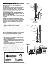
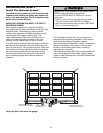
ALIGNING THE SAFETY REVERSING SENSORS
and opener.
• Plug in the opener. The indicator lights in both the
• A broken wire.
sending and receiving eyes will glow steadily if wiring
2. If the sending eye indicator light glows steadily but the
connections and alignment are correct.
receiving eye indicator light doesn't:
The sending eye amber indicator light will glow
• Check alignment.
regardless of alignment or obstruction. If the green
indicator light in the receiving eye is off, dim, or flickering
• Check for an open wire to the receiving eye.
(and the invisible light beam path is not obstructed),
3. If the receiving eye indicator light is dim, realign
alignment is required.
either sensor.
• Loosen the sending eye wing nut and readjust, aiming
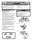
NOTE: When the invisible beam path is obstructed or
directly at the receiving eye. Lock in place.
misaligned while the door is closing, the door will
• Loosen the receiving eye wing nut and adjust the safety
reverse. If the door is already open, it will not close.
reversing sensor until it receives the sender’s beam.
The remote lights will blink 10 times. (If bulbs are not
When the green indicator light glows steadily, tighten
installed, 10 clicks can be heard.) See page 11.
the wing nut.
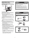
Bell Wire
Motor unit
Figure 6
Bell Wire
To CableTension Monitor
Connect Wire to
To Power
Quick-Connect
Terminals
Door Lock
Power Door Lock
Connections
Sensor
WHT/RED
WHT/BLK
WHT
WHT
Quick-Connect Terminals
To Door Control
To insert or release wires, push
in tab with screwdriver tip.
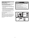
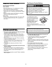
Safety Reversing Sensor
Sensor
Invisible Light Beam
S
ensor
Protection Area
Safety Reversing Sensor
16