


8
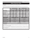
Aspen Woodburning Stove
30000369
ST275
wall with
ventilated
steel thimble
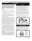
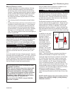
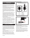
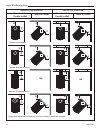
Fig. 12 Wall Pass-through with ventilated steel thimble.
24 ga. Sheet
Steel Supports
24 ga. Sheet
Steel Supports
2” (51mm) Min.
Chimney clearance to sheet steel
supports and combustibles
2” (51mm)
Min.
Chimney Flue
2” (51mm) Min.
air space
Prefab Chim-
ney
Section
Prefab
Chimney
Section
Chimney Con-
nector
Masonry Chimney construct-
ed to NFPA 211
ST275
U.S. Requirements:
The National Fire Protection Association (NFPA) has
established guidelines for use in the United States for
passing chimney connectors through combustible walls.
Many building code inspectors follow these guidelines.
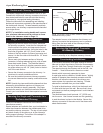
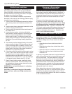
Figure 9 shows one NFPA-approved method. All com-
bustible material in the wall is cut away to provide 12”
(305 mm) clearance to the connector. Brick and mortar
are used to enclose the clearance area.
Alternate methods approved by the NFPA:
• Using a section of double-wall chimney with a 9”
(229 mm) clearance to combustibles. (Fig. 10)
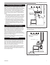
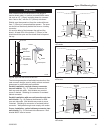
• Placing a chimney connector pipe inside a steel
double-wall ventilated thimble, which is then sepa-
rated from combustibles by 6” (152 mm) of fiberglass
insulating material. (Fig. 11)
• Placing a chimney connector pipe inside a section of
9” (229 mm) diameter, solid-insulated, factory-built
chimney, with two inches of air space between the
chimney section and combustibles. (Fig. 12)
Canadian Requirements:
In Canada, the Canadian Standards Association has
established specific guidelines regarding wall pass-
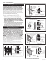
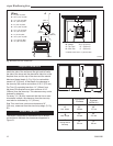
though design. Figure 13 shows one approved method
in which all combustible material in the wall is cut away
to provide the required 18” (457 mm) clearance around
the connector. The resulting space must remain empty.
A flush-mounted sheet metal cover may be used on one
side only. If covers must be used on both sides, each
cover must be mounted on noncombustible spacers at
least 1” (25 mm) clear of the wall. Your local dealer or
your local building inspector can provide details of other
approved methods of passing a chimney connector
through a combustible wall.
In Canada, this type of installation must conform to
CAN/CSA-B365, Installation Code for Solid Fuel Burn-
ing Appliances and Equipment.
ST272
masonry wall pass through
w/ single wall
connector
12/99
Min. 2” (51mm) Chimney clear-
ance to brick and combustibles
A = Minimum 12” (305 mm) brick con-
struction between liner and combustible
framing materials
Min. 12”
(305 mm)
Fire clay
liner
A
A
Chimney Flue
Fire clay liner
Masonry
Chimney
constructed
to NFPA 211
Fig. 9 Masonry Wall Pass-through with single wall
chimney connector.
Chimney
connector
ST272
ST274
single wall
w/ventilated thimble
12/99
Fig. 11 Wall Pass-through using single wall chimney
connector with a ventilated steel thimble.
Min. 6”
(152mm)
Chimney clearance to sheet steel
supports and combustibles
2” (51mm) Min.
Glass Fiber
Insulation
Chimney Connector
Chimney Flue
Steel Thimble
with two 1”
(25mm) Ventilated
Channels
Masonry Chimney construct
-
ed to NFPA 211
24 ga.Sheet
Steel Supports
ST274
ST276
CSA approved wall
pass-through
12/99
Fig. 13 CSA approved Wall Pass-through.
24 ga.Sheet
Steel Support
24 ga. Sheet
Steel Support
(one side only)
Min. 18”
(460mm)
Chimney clearance to sheet steel
supports and combustibles
2” (51mm)
Min.
Chimney Flue
Chimney
Connector
Masonry Chimney constructed
to CAN/CSA-B365
Min. 18”
(460mm)
ST276
ST273
nfpa
factory built insulated
chimney section
12/99
Fig. 10 Wall Pass-through using factory-built insulated
chimney section.
Min. 9”
(230mm)
Air Space
Min. 9”
230mm
Chimney Flue
Sheet Steel
Supports
Min. 2”
(51mm)
Non-soluble re-
fractory cement
Solid insulated,
listed factory-
built chimney
length set flush
with flue
Chimney
Connector
Masonry
Chimney
constructed to
NFPA 211
24 ga.Sheet
Steel Sup-
ports
ST273