


13
Aspen Woodburning Stove
30000369
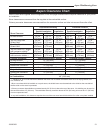
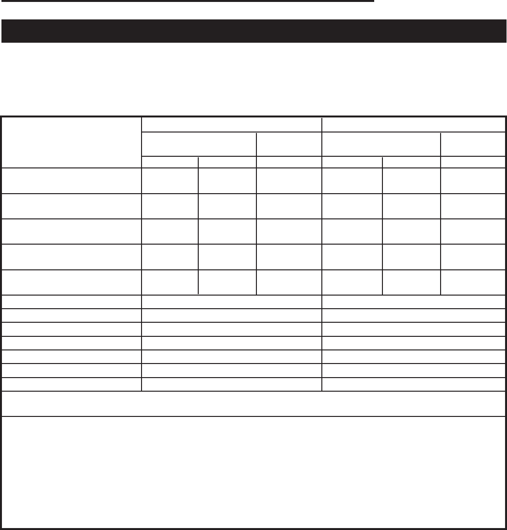
Aspen Clearance Chart
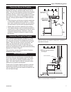
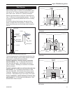
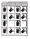
Use the chart below together with the diagrams on the next page to determine the required clearance for your particu-
lar installation.
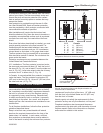
Stove clearances are measured from the top plate to the combustible surface.
Chimney connector clearances are measured from the connector surface and take into account flue collar offset.
** A distance of 48” must be maintained between the stove and moveable combustible items such as drying clothes, furni-
ture, firewood, etc.
1
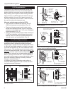
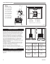
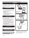
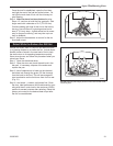
When a rear heat shield is installed on a top exit stove, the shield insert must be attached to the shield so the area behind
the flue collar on the stove is protected.
2
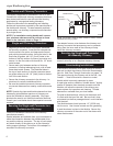
Chimney connector heat shields must extend exactly 24” (610 mm) above the top of the stove. No shielding can be used on
the connector above 24” (610 mm). The unshielded chimney connector above the 24” (610 mm) point must be 13” (330 mm)
from an unprotected wall.
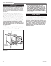
3
In top exit installations, this clearance requires the use of the rear stove heat shield with the flue collar cover plate installed.
Unprotected Surfaces Protected Surfaces
Corner Corner
Parallel Installation Installation Parallel Installation Installation
Stove Clearance Side Rear Corner Side Rear Corner
No Heat Shields (A) 24” (B) 13” (C) 13” (D) 16” (E) 9” (F) 8”
(610 mm) (330 mm) (330 mm) (406 mm) (230 mm) (203 mm)
Top Exit, Rear Heat (G) 24” (H) 11” (I) 13” (J) 16” (K) 9” (L) 8”
Shield ONLY
1
(610 mm) (179 mm) (330 mm) (406 mm) (230 mm) (203 mm)
Rear Exit, Rear Heat (M) 24” (N) 11” N/A (O) 16” (P) 9” N/A
Shield ONLY (610 mm) (179 mm) (406 mm) (230 mm)
Top Exit, Rear H.S., Single- (Q) 24” (R) 9” (S) 13” (T) 16” (U) 9” (V) 8”
wall, connector shields
1,2
(610 mm) (229 mm) (330 mm) (406 mm) (230 mm) (203 mm)
Top Exit, Rear H.S., Double- (Q) 24” (R) 7” (S) 13” (T) 16” (U) 7” (V) 8”
wall connector shields
1,3
(610 mm) (178 mm) (330 mm) (406 mm) (178 mm) (203 mm)
Chimney Connector Unprotected Surface / Vertical Protected Surface / Vertical
No Heat Shields 15” (381 mm) 11” ( 279 mm)
Using Connector Heat Shields
2
13” (330 mm) 6” (152 mm)
Double Wall Connector
3
6” (152 mm) 6” (152 mm)
Unprotected Surface / Horizontal Protected Surface / Horizontal
Single Wall Connector 18” (457 mm) 11” (279 mm)
Double Wall Connector 6” (152 mm) 6” (152 mm)
Front Clearance All Installations
to Combustibles 48” (1219 mm)