


12
Aspen Woodburning Stove
30000369
ST252a
mantel clrncs
12/14/99 djt
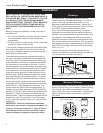
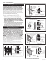
When:
A = 9” (229 mm) Max.
B = 22¹⁄₂" (572 mm) Min.
A = 7¹⁄₂" (191 mm) Max.
B = 21” (533 mm) Min.
A = 6” (152 mm) Max.
B = 19¹⁄₂" (495 mm) Min.
A = 4¹⁄₂" (114 mm) Max.
B = 18” (457 mm) Min.
A = 3” (76 mm) Max.
B = 16¹⁄₂" (419 mm) Min.
A = 1¹⁄₂" (38 mm) Max.
B = 15” (381 mm) Min.
Min. 15”
(381mm)
1¹/₂"
(38mm)
Max. 9”
(229mm)
22¹/₂"
(572mm)
A
B
ST252a
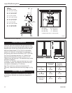
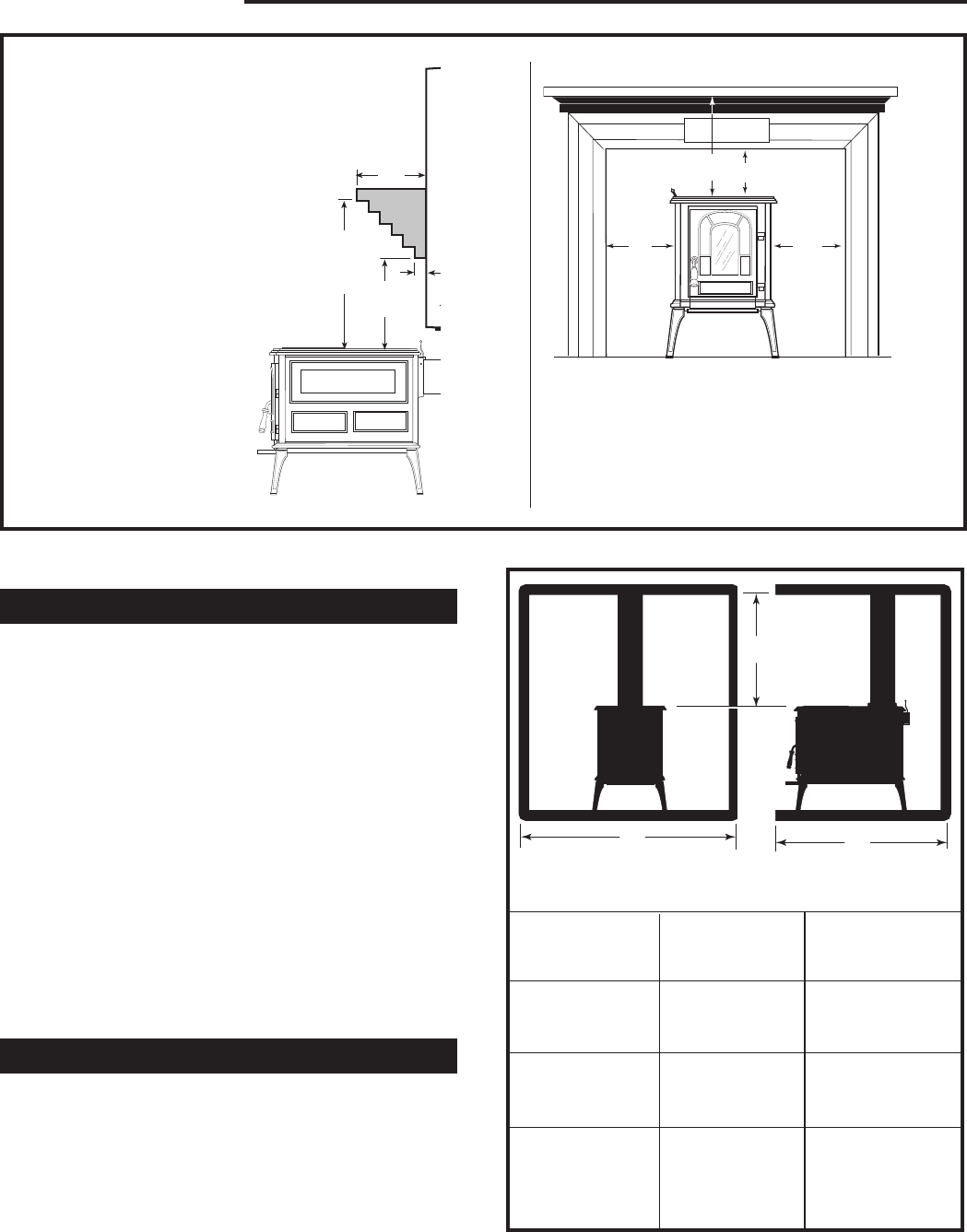
Fireplace Clearances
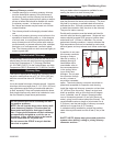
A fireplace installation requires special clearance be-
tween the side of the stove and the right and left walls,
the side of the stove and the decorative side trim on the
fireplace face, and the top of the stove and the mantel.
Maximum Mantel depth (A, Fig. 20) of a combustible
mantel is 9” (230 mm). At that depth, the clearance to
the stove top (B) must be a minimum of 22¹⁄₂" (572 mm).
Top Trim (C) protruding less than 1¹⁄₂" (38mm) from
the face of the fireplace must be a minimum of 12"
(305mm) from the stove top. This clearance may not be
reduced by shielding.
For every 1¹⁄₂" (38 mm) increment that the trim or man-
tel extends in depth, the clearance from the stove top
must also be increased by 1¹⁄₂" (38 mm).
Side Trim must have a minimum clearance of 8"
(203 mm), measured from the stove's top edge. (D, Fig.
20)
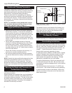
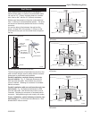
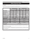
Alcove Clearances
The Aspen is approved for installation into an alcove
constructed to maintain the clearances diagramed in
Figure 21.
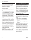
Fig. 20 Mantel and trim clearances.
B: Mantel 22¹⁄₂" (572 mm)
C: Top Trim* 12” (305 mm)
D: Side Trim 8” (203 mm)
* material is less than 1¹⁄₂" (38 mm) thick
ST253a
aspen
trim clearances
12/15/99 djt
C
D
D
B
ST253a
ST254
alcove clearances
12/99
Fig. 21 Alcove Specifications.
Unprotected
Surfaces
Protected
Surfaces
(NFPA 211)
A
Min. Width
B
Max. Depth
C
Ceiling Above
Stovetop
62”
158 cm
46”
117 cm
48”
122 cm
48”
122 cm
36”
92 cm
18”
46 cm
B
A
C
ST254