


15
Aspen Woodburning Stove
30000369
ST257
install ashlip
12/99
1/4-20 x ⁵/₈” hex head
screws with washers
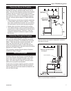
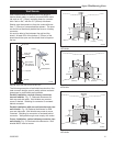
Fig. 23 Attach the Ashlip to the bottom plate.
ST257
2. Locate the hex bolt (Fig. 23) located in the center
rear edge of the stove bottom plate. Loosen this bolt
just enough to engage the Adapter clevis tab under
the washer and then retighten.
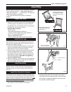
You will need the following tools to assemble the Aspen:
• 9/16” open end wrench • safety glasses & gloves
• flat head screwdriver • power drill w/ 1/8” (3mm) bit
• stub handle phillips screwdriver
• 7/16” open end wrench (for Ashlip & Outside Air
Adapter)
Unpack the Stove
1. Remove the shipping straps and plastic wrap.
2. Inspect the stove and contents for shipping damage
or missing parts. Immediately notify your dealer of
any damage. Do not install this stove if any damage
is evident or any parts are missing.
Hardware Bag contents:
• Stove Legs, 4
• Hex Head Leg bolts with washers, 4
• 1/4-20 x 5/8” hex head screws with washers, 2
• #10 x 1/2” sheet metal screws, 3
• Owner’s Registration Card
• Touch-up Paint (Porcelain enamel stoves only)
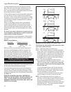
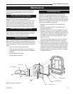
Install Stove Legs
Leg installation will be accomplished most easily with
the help of an assistant who can tilt the stove onto its
side while you attach the legs.
1. With your assistant holding the stove up on its side,
remove the slotted screws from the leg mounting
holes at each corner of the stove bottom.
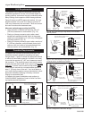
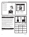
2. Install two legs, using the hex head bolts with wash-
ers from the parts bag. The shoulder of the legs
should seat within the locator bosses cast into the
stove bottom at each corner. (Fig. 22) Tighten the
bolts with the wrench. CAUTION: Overtighening
can strip tapped threads.
3. With your assistant, lift the stove up onto its legs and
hold it in a tilted position to install the remaining two
legs with washers and hex bolts.
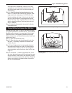
Install the Ashlip
Use a 7/16” wrench to secure the Ashlip to the stove
bottom with two, 1/4-20 x 5/8” hex head screws and
washers found in the hardware bag inside the stove.
(Fig. 23)
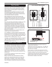
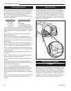
Install the Outside Air Adapter
The optional #1897 Outside Air Adapter provides a col-
lar to which a 3 inch diameter air duct may be attached
directly to the air inlet area at the back of the stove. The
adapter should be attached to the stove before a bot-
tom or rear heat shield is installed.
1. Remove the phillips head screw located just above
the primary air inlet at the back of the stove.
ST256
attach legs
12/15/99 djt
Carefully tilt the stove
on the pallet to install
first one front and one
rear leg.
Then tilt the stove up on
those legs to install the
remaining two.
ST256
Fig. 22 Install legs on one side of stove then the other.
Assembly
ST258
install outside
adapter
12/15/99 djt
Fig. 24 Attach the adapter to the bottom plate.
Loosen Hex Bolt
Adapter
ST258