


7
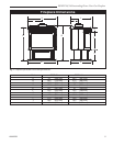
RFSDV24/34 Freestanding Direct Vent Gas Fireplace
10003550
CFM106
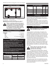
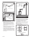
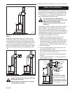
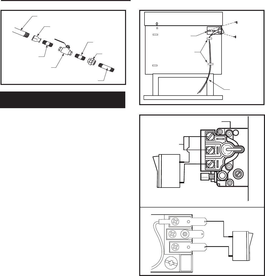
Typical Gas Line Connection
9-29-00
1/2” Gas Supply
1/2” x 3/8” Reducer
3/8” Nipple
3/8” x 3/8”
Shut-Off Valve
3/8” Nipple
3/8” Union
3/8” Nipple
CFM106
Fig. 3 Typical gas line connection.
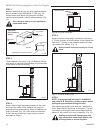
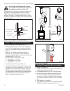
Installation of Remote Switch
for RN/RP Gas Valve
NOTES: The remote ON/OFF switch cannot be fit-
ted to units using the Honeywell Radio Frequency
control valve.
If the fireplace has been fitted with the Radio
Frequency Control Valve, the ON/OFF function is
controlled by the remote handset. (Refer to the ad-
dendum or instructions packaged with the remote
handset.)
Install the ON/OFF switch assembly on either the rear
right or rear left side of the fireplace.
1. Remove the screw at the back of the cabinet top
either on the left or the right side of the fireplace.
2. Position switch assembly onto the back of the fire-
place, then fasten two (2) screws as shown in Figure
3.
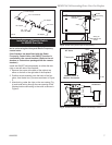
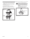
3. Attach wiring under the clips on the rear casing (Fig.
4) and install wiring through the rear opening of the
fireplace before connecting to the valve as shown in
Figure 5.
ON/OFF Switch
Assembly
Clips
Screw
Screw
(through existing
hole)
Wiring for
Millivolt Gas
Valves
FP1621
Fig. 4 Attach wiring under clips on rear casing.
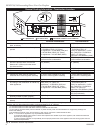
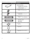
P
I
L
O
T
TPTH
TP
TH
Valve
Thermopile
FP1622
ON/OFF Switch or
Millivolt Thermostat
PILOT
ADJ
TH
TP
TP
TH
rev 06-02
rjs
SIT Valve
RN/RP Valve
FP1494
Fig. 5 Install wiring to switch before connecting to valve.