


19
RFSDV24/34 Freestanding Direct Vent Gas Fireplace
10003550
RN/RP Models
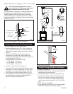
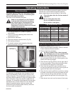
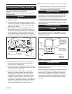
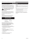
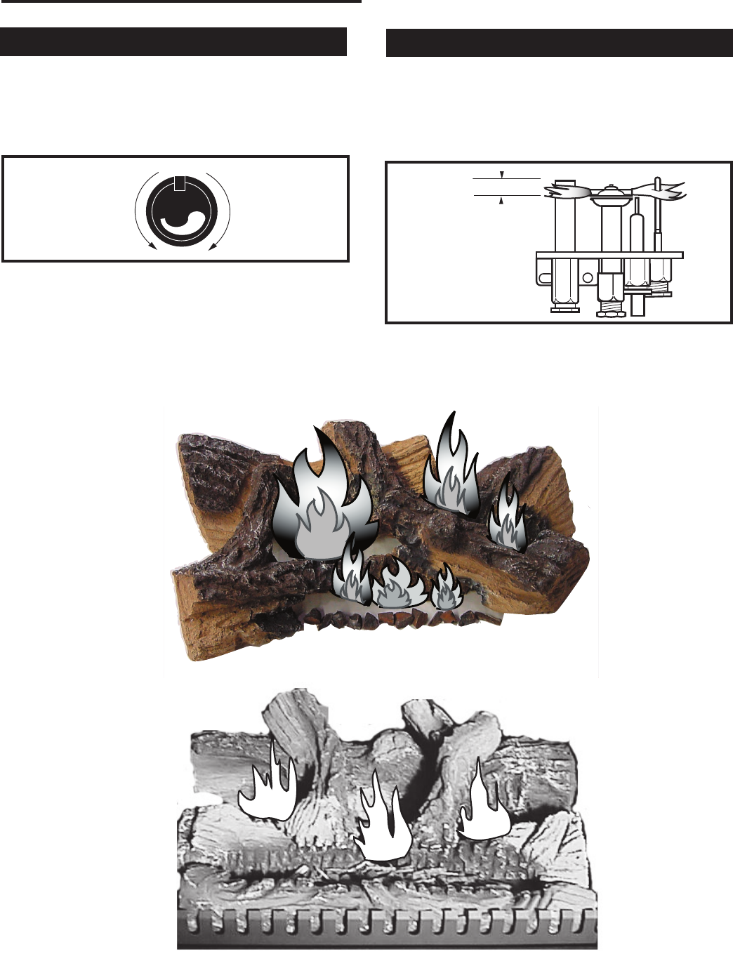
For units equipped with ‘HI/LO’ valves the flame
adjustment is accomplished by rotating the ‘HI/LO’
adjustment knob located near the center of the gas
control valve. (Fig. 29)
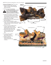
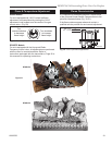
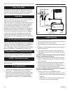
It is important to periodically perform a visual check
of the pilot and burner flames. Compare them to the
pictorials illustrated below (Fig. 30-31).
If the flame patterns appear abnormal contact a
qualified service provider for service and adjustment.
Flame Characteristics
Flame & Temperature Adjustment
Turn
counterclockwise
to decrease
flame height
Turn clockwise
to increase
flame height
HV102
Honeywell hi/lo knob
4/5/99 djt
Fig. 29 Flame adjustment knob for Honeywell valve.
F584-703
Honeywell
& PSE
pilot flames
3/8” - 1/2”
(10 - 13 mm)
F584-703
Fig. 30 Correct pilot flame appearance.
RFN/RFP Models
For units equipped with the Honeywell Radio
Frequency control valve, all adjustments are performed
with the use of a remote transmitter. Refer to
instructions packaged with the transmitter or Page 20 in
this manuals for operating instructions.
LG347
RFSDV34
log flames
6/04
LG346
24RFSDV LOG flames
6/04
RFSDV24
RFSDV34
Figure 31
LG346
LG347